R&S
®
ZVA / R&S
®
ZVB / R&S
®
ZVT GUI Reference
Channel Menu
Operating Manual 1145.1084.12 – 30 400
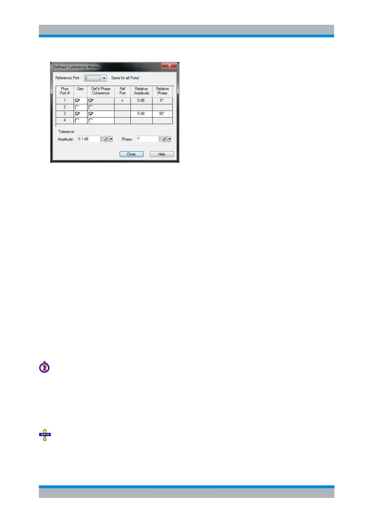
Reference Port selects one of the physical analyzer ports as a reference port. The reference port
is the source port for the reference signal; its properties are defined in the Port Configuration
dialog. The amplitude and phase of all coherent signals are defined relative to the reference
signal.
Gen ensures a permanent signal; it is identical with the Gen setting in the Source section of the
Port Configuration dialog. Coherent signals must be permanent. System error corrections must be
performed with alternating source signals (Gen off).
Def'd Phase Coherence defines the signals from the analyzer ports as coherent or non-coherent
signals. For coherent signals, the specified amplitude and phase relation is maintained across the
entire sweep. Non-coherent signals have an arbitrary relative phase. It is possible to select one
signal per internal source as a coherent signal; see Coupled Test Ports.
In converter mode all converter ports must be configured for active power control, i.e. the power
control method must not be set to None or Mechanical Attenuator.
Examples: On a four port analyzer, ports 1 and 2 and ports 3 and 4 uses the same generator
(coupled ports). If port 1 is the reference port, either port 3 or port 4 can be selected as the source
port for the second, coherent signal.
Relative Amplitude defines the amplitude of the coherent signals relative to the reference signal.
The Relative Amplitude replaces the source power of the port (defined in the Port Configuration
dialog)) as long as Def'd Phase Coherence is selected.
Relative Phase defines the phase of the coherent signals relative to the phase of the reference
signal; see below.
Tolerance defines the maximum deviation from the defined Amplitude and Phase relation of the
coherent signals.
Amplitude and phase tolerance for true differential mode and defined coherence mode
In True Differential Mode and Defined Coherence Mode one of the two involved ports serves as a
reference port, while amplitude and phase of the other port is adjusted until the desired amplitude and
phase difference is reached (e.g. 0 dB and 180° for True Differential Mode).
The tolerances define the maximum allowed deviation between nominal and actual amplitude and phase
differences. By default the adjustment stops if the desired amplitude and phase differences are met with a
tolerance of 0.1 dB and 1°, respectively.
Note that the tolerance settings apply to both the True Differential Mode and the Defined Coherence
Mode.