RL78/G1H CHAPTER 6 CLOCK GENERATOR
R01UH0575EJ0120 Rev. 1.20 Page 109 of 920
Dec 22, 2016
Figure 6 - 6 Format of Oscillation stabilization time select register (OSTS)
Caution 1. Change the setting of the OSTS register before setting the MSTOP bit of the clock operation status
control register (CSC) to 0.
Caution 2. The oscillation stabilization time counter counts up to the oscillation stabilization time set by the
OSTS register.
In the following cases, set the oscillation stabilization time of the OSTS register to the value greater
than the count value which is to be checked by the OSTC register after the oscillation starts.
• When the X1 clock starts oscillation while the high-speed on-chip oscillator clock or subsystem
clock is being used as the CPU clock.
• When the STOP mode is entered and then released while the high-speed on-chip oscillator clock is
being used as the CPU clock with the X1 clock oscillating. (Note, therefore, that only the status up
to the oscillation stabilization time set by the OSTS register is set to the OSTC register after the
STOP mode is released.)
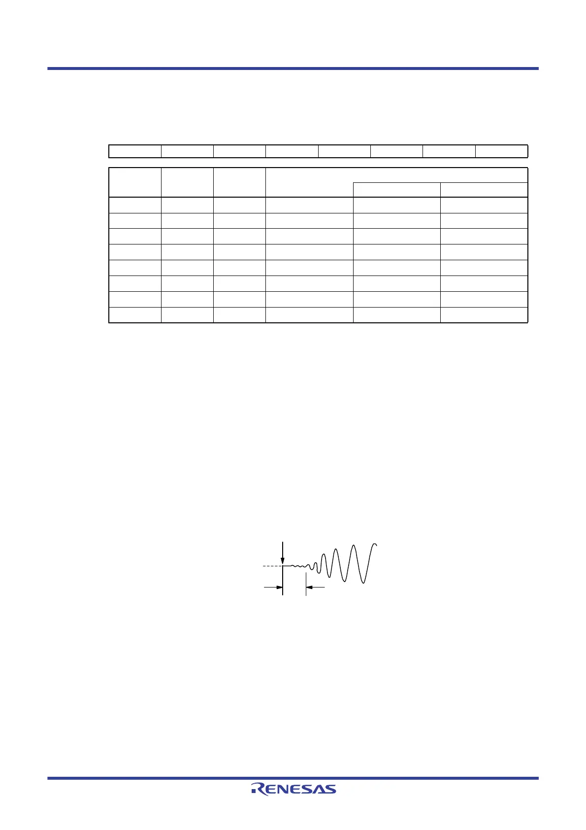
Caution 3. The X1 clock oscillation stabilization wait time does not include the time until clock oscillation starts
(“a” below).
Remark
fX: X1 clock oscillation frequency
Address: FFFA3H After reset: 07H R/W
Symbol76543210
OSTS00000OSTS2OSTS1OSTS0
OSTS2 OSTS1 OSTS0
Oscillation stabilization time selection
f
X = 10 MHz fX = 20 MHz
000
2
8
/fX
25.6 μs12.8 μs
001
2
9
/fX
51.2 μs25.6 μs
010
2
10
/fX
102 μs51.2 μs
011
2
11
/fX
204 μs102 μs
100
2
13
/fX
819 μs409 μs
101
2
15
/fX
3.27 ms 1.63 ms
110
2
17
/fX
13.1 ms 6.55 ms
111
2
18
/fX
26.2 ms 13.1 ms
STOP mode release
X1 pin voltage
waveform
a
 Loading...


