RL78/G1H CHAPTER 11 CLOCK OUTPUT/BUZZER OUTPUT CONTROLLER
R01UH0575EJ0120 Rev. 1.20 Page 270 of 920
Dec 22, 2016
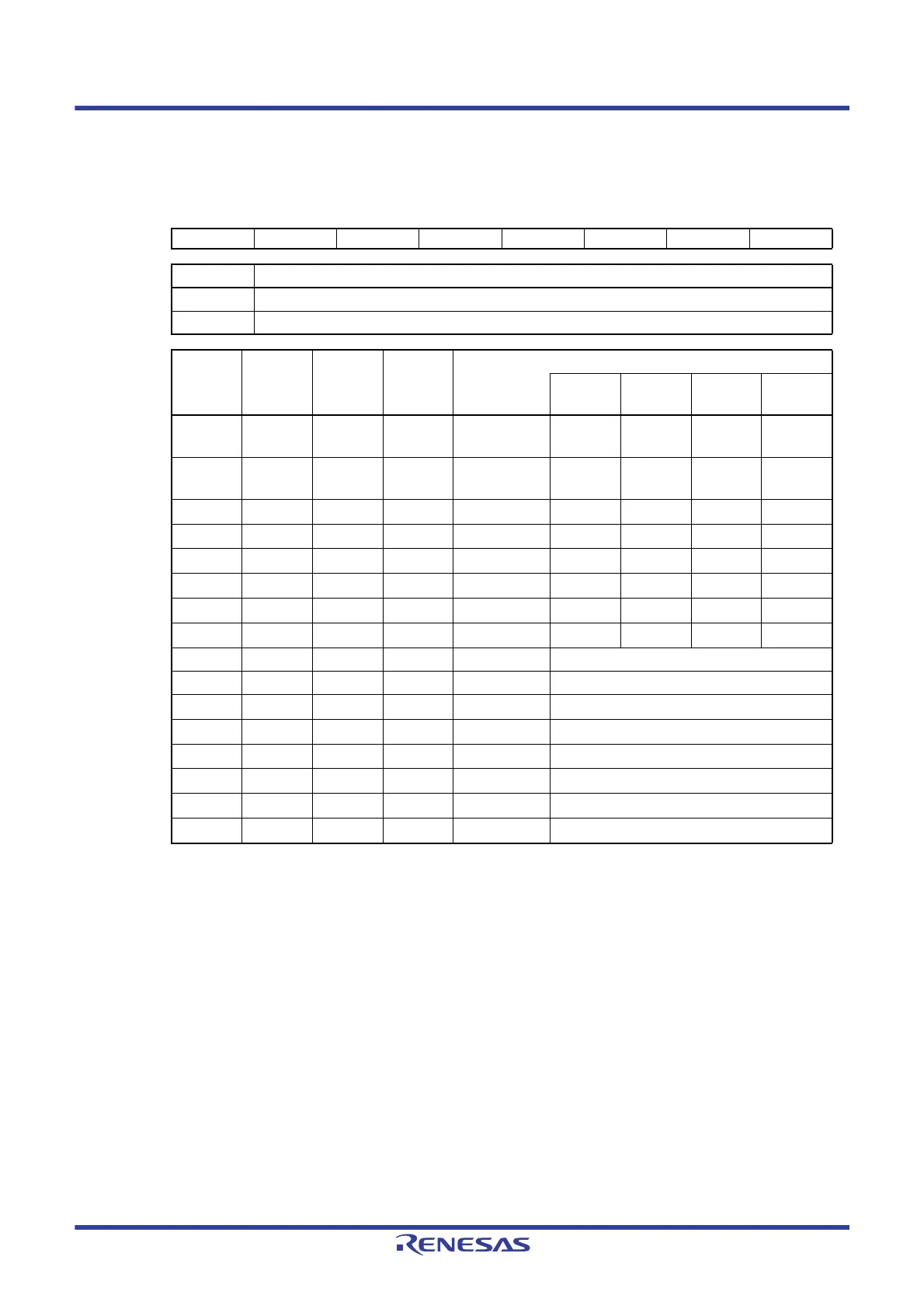
Figure 11 - 2 Format of Clock output select registers n (CKSn)
Note Use the output clock within a range of 8 MHz. See 31.4 AC Characteristics for details.
Caution 1. Change the output clock after disabling clock output (PCLOEn = 0).
Caution 2. To shift to STOP mode when the main system clock is selected (CSELn = 0), set PCLOEn = 0 before
executing the STOP instruction. When the subsystem clock is selected (CSELn = 1), PCLOEn = 1 can
be set because the clock can be output while RTCLPC in the subsystem clock supply mode control
register (OSMC) = 0 in STOP mode.
Caution 3. In HALT mode when RTCLPC in the subsystem clock supply mode control register (OSMC) = 1 and
while the subsystem clock (f
SUB) is used for CPU operation, it is not possible to output the
subsystem clock (f
SUB) from the PCLBUZn pin.
Remark 1.
n = 0, 1
Remark 2. fMAIN: Main system clock frequency
f
SUB: Subsystem clock frequency
Address: FFFA5H (CKS0), FFFA6H (CKS1) After reset: 00H R/W
Symbol<7>6543210
CKSn PCLOEn 0 0 0 CSELn CCSn2 CCSn1 CCSn0
PCLOEn PCLBUZn pin output enable/disable specification
0 Output disable (default)
1 Output enable
CSELn CCSn2 CCSn1 CCSn0 PCLBUZn pin output clock selection
f
MAIN =
5 MHz
fMAIN =
10 MHz
fMAIN =
20 MHz
fMAIN =
32 MHz
0000 f
MAIN
5 MHz
Note
Setting
prohibited
Setting
prohibited
Setting
prohibited
0001f
MAIN/2 2.5 MHz
5 MHz
Note
Setting
prohibited
Setting
prohibited
0010
f
MAIN/2
2
1.25 MHz 2.5 MHz
5 MHz
Note
8 MHz
Note
0011
f
MAIN/2
3
625 kHz 1.25 MHz 2.5 MHz 4 MHz
0100
f
MAIN/2
4
312.5 kHz 625 kHz 1.25 MHz 2 MHz
0101
f
MAIN/2
11
2.44 kHz 4.88 kHz 9.77 kHz 15.63 kHz
0110
f
MAIN/2
12
1.22 kHz 2.44 kHz 4.88 kHz 7.81 kHz
0111
f
MAIN/2
13
610 Hz 1.22 kHz 2.44 kHz 3.91 kHz
1000 f
SUB 32.768 kHz
1001f
SUB/2 16.384 kHz
1010
f
SUB/2
2
8.192 kHz
1011
f
SUB/2
3
4.096 kHz
1100
f
SUB/2
4
2.048 kHz
1101
f
SUB/2
5
1.024 kHz
1110
f
SUB/2
6
512 Hz
1111
f
SUB/2
7
256 Hz
 Loading...


