RL78/G1H CHAPTER 3 PIN FUNCTIONS
R01UH0575EJ0120 Rev. 1.20 Page 20 of 920
Dec 22, 2016
Set in each port I/O, buffer, pull-up resistor is also valid for alternate functions.
Note 1. Input of A/D converter is not supported.
Note 2. Each pin can be specified as digital I/O port by setting port mode control register x (PMCx) (Can be specified in 1-bit
units).
Note 3. This pin is used for connection between the MCU and RF transceiver. For details, refer to CHAPTER 2 CONNECTION
BETWEEN MCU AND RF TRANSCEIVER
.
Note 4. Each pin can be specified as either digital or analog by setting the A/D port configuration register (ADPC).
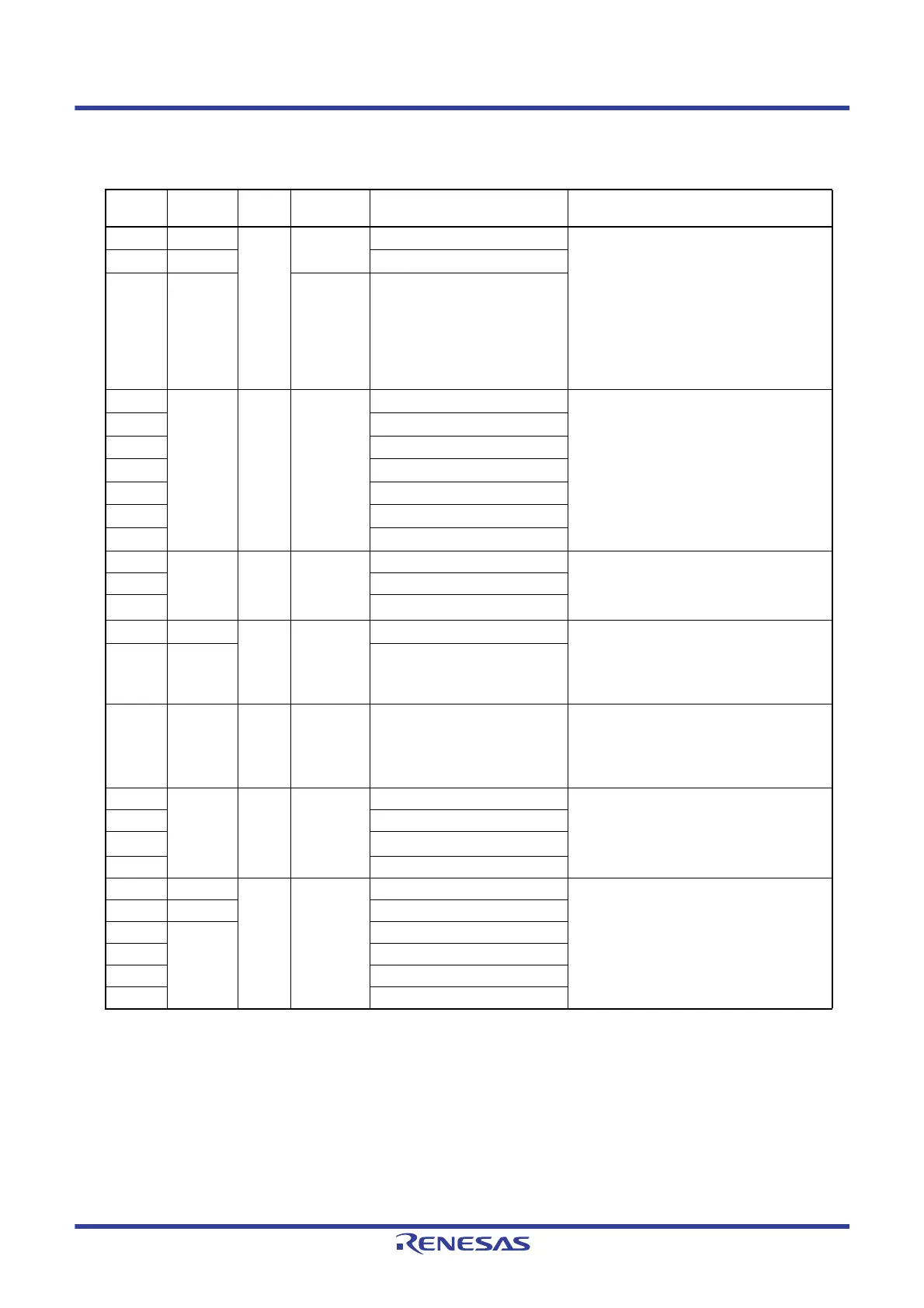
(1/2)
Function
Name
Pin Type I/O
After Reset
Release
Alternate Function Function
P02
7-3-4
Note 1
I/O Prohibit
I/O
Note 2
SO10/TxD1 Port 0.
3-bit I/O port.
Input/output can be specified in 1-bit units.
Use of an on-chip pull-up resistor can be specified by
a software setting at input port.
Input of P03 and P04 can be set to TTL input buffer.
Output of P02 to P04 can be set to N-ch open-drain
output (V
DD tolerance).
The digital I/O of P02 and P03 is prohibited at the
reset release
Note 2
.
P03
8-3-4
Note 1
SI10/RxD1
P04 8-1-4 Input port SCK10
P10
Note 3
— I/O Input port — Port 1.
7-bit I/O port.
Input/output can be specified in 1-bit units.
Use of an on-chip pull-up resistor can be specified by
a software setting at input port.
P11
Note 3
—
P12
Note 3
—
P13
Note 3
SO20
P14
Note 3
SI20
P15
Note 3
SCK20
P16
Note 3
—
P20 4-3-3 I/O Analog
function
ANI0/AV
REFP Port 2.
3-bit I/O port.
Input/output can be specified in 1-bit units.
Can be set to analog input
Note 4
.
P21 ANI1/AV
REFM
P22 ANI2
P30
Note 3
8-1-4 I/O Input port INTP3 Port 3.
2-bit I/O port.
Input/output can be specified in 1-bit units.
Use of an on-chip pull-up resistor can be specified by
a software setting at input port.
P31 7-1-3 TI03/TO03/INTP4
P40 7-1-3 I/O Input port TOOL0 Port 4.
1-bit I/O port.
Input/output can be specified in 1-bit units.
Use of an on-chip pull-up resistor can be specified by
a software setting at input port.
P60 12-1-2 I/O Input port SCLA0 Port 6.
4-bit I/O port.
Input/output can be specified in 1-bit units.
Output of P60 to P63 is N-ch open-drain output
(6 V tolerance).
P61 SDAA0
P62
SCLA1
P63 SDAA1
P70 7-1-3 I/O Input port SCK21 Port 7.
6-bit I/O port.
Input/output can be specified in 1-bit units.
Use of an on-chip pull-up resistor can be specified by
a software setting at input port.
Output of P71 can be set to N-ch open-drain output
(V
DD tolerance).
P71 7-1-4 SI21
P72 7-1-3 SO21
P75 NTP9
P76 INTP10
P77 INTP11
 Loading...


