RL78/G1H CHAPTER 18 RF TRANSCEIVER
R01UH0575EJ0120 Rev. 1.20 Page 631 of 920
Dec 22, 2016
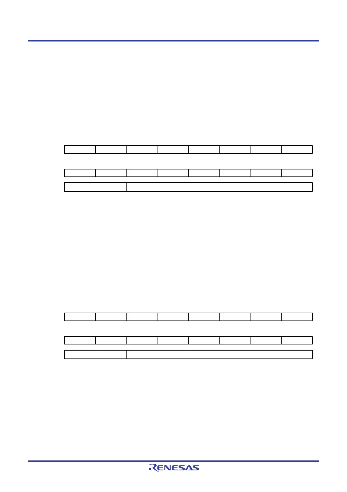
(66) ANT0 read register (BBANT0RD)
This register is used to store the RSSI value when the ANTSELOUT0 pin output is at the high level.
The reading value is corresponding save bank specified by receive data save bank select bit.
The value is set as 2’s complement. The setting unit is dBm (ex. ”19EH” is ”-98dBm”).
BBANT0RD register is set via serial interface in 8-bit units.
Reset signal generation sets this register to 0100H.
Figure 18 - 79 ANT0 Read Register (BBANT0RD) Format
Caution “0” is always read for bits 9 to 15.
(67) ANT1 read register (BBANT1RD)
This register is used to store the RSSI value when the ANTSELOUT1 pin output is at the high level.
The reading value is corresponding save bank specified by receive data save bank select bit.
The value is set as 2’s complement. The setting unit is dBm (ex. ”19EH” is ”-98dBm”).
BBANT1RD register is set via serial interface in 8-bit units.
Reset signal generation sets this register to 0100H.
Figure 18 - 80 ANT1 Read Register (BBANT1RD) Format
Caution “0” is always read for bits 9 to 15.
Address:
00C9H, 00C8H
After reset:
0100H
R
Symbol 15 14 13 12 11 10 9 8
BBANT0RD
0000000ANT0RD8
76543210
ANT0RD7 ANT0RD6 ANT0RD5 ANT0RD4 ANT0RD3 ANT0RD2 ANT0RD1 ANT0RD0
ANT0RD[8:0] RSSI value when the ANTSELOUT0 pin output is at the high level
Address:
00CBH, 00CAH
After reset:
0100H
R
Symbol 15 14 13 12 11 10 9 8
BBANT1RD
0000000ANT1RD8
76543210
ANT1RD7 ANT1RD6 ANT1RD5 ANT1RD4 ANT1RD3 ANT1RD2 ANT1RD1 ANT1RD0
ANT1RD[8:0] RSSI value when the ANTSELOUT1 pin output is at the high level
 Loading...


