RL78/G1H CHAPTER 19 INTERRUPT FUNCTIONS
R01UH0575EJ0120 Rev. 1.20 Page 713 of 920
Dec 22, 2016
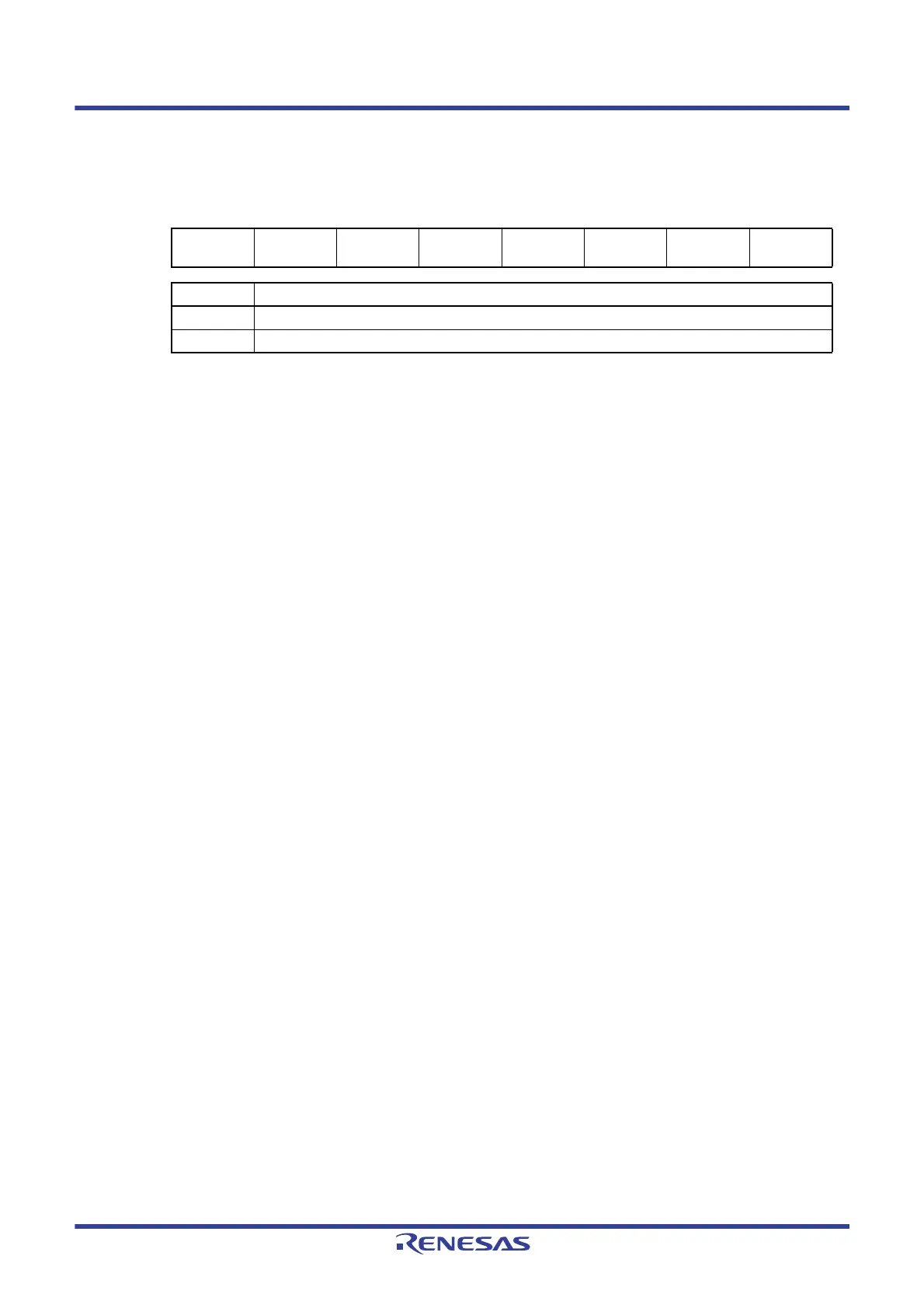
Figure 19 - 3 Format of Interrupt Request Flag Registers (IF0L, IF0H, IF1L, IF1H, IF2L, IF2H) (2/2)
Caution 1. The available registers and bits differ depending on the product. For details about the registers and
bits available for each product, see Tables 19 - 3 to 19 - 5. Be sure to set bits that are not available to
the initial value.
Caution 2. When manipulating a flag of the interrupt request flag register, use a 1-bit memory manipulation
instruction (CLR1). When describing in C language, use a bit manipulation instruction such as
“IF0L.0 = 0;” or “_asm (“clr1 IF0L, 0”);” because the compiled assembler must be a 1-bit memory
manipulation instruction (CLR1).
If a program is described in C language using an 8-bit memory manipulation instruction such as
“IF0L &= 0xfe;” and compiled, it becomes the assembler of three instructions.
mov a, IF0L
and a, #0FEH
mov IF0L, a
In this case, even if the request flag of the another bit of the same interrupt request flag register
(IF0L) is set to 1 at the timing between “mov a, IF0L” and “mov IF0L, a”, the flag is cleared to 0 at
“mov IF0L, a”. Therefore, care must be exercised when using an 8-bit memory manipulation
instruction in C language.
Address: FFFD1H After reset: 00H R/W
Symbol <7> <6> 5 <4> 3 2 1 <0>
IF2H FLIF IICAIF1 0
SREIF3
TMIF13H
000PIF11
XXIFX Interrupt request flag
0 No interrupt request signal is generated
1 Interrupt request is generated, interrupt request status
 Loading...


