RL78/G1H CHAPTER 20 STANDBY FUNCTION
R01UH0575EJ0120 Rev. 1.20 Page 745 of 920
Dec 22, 2016
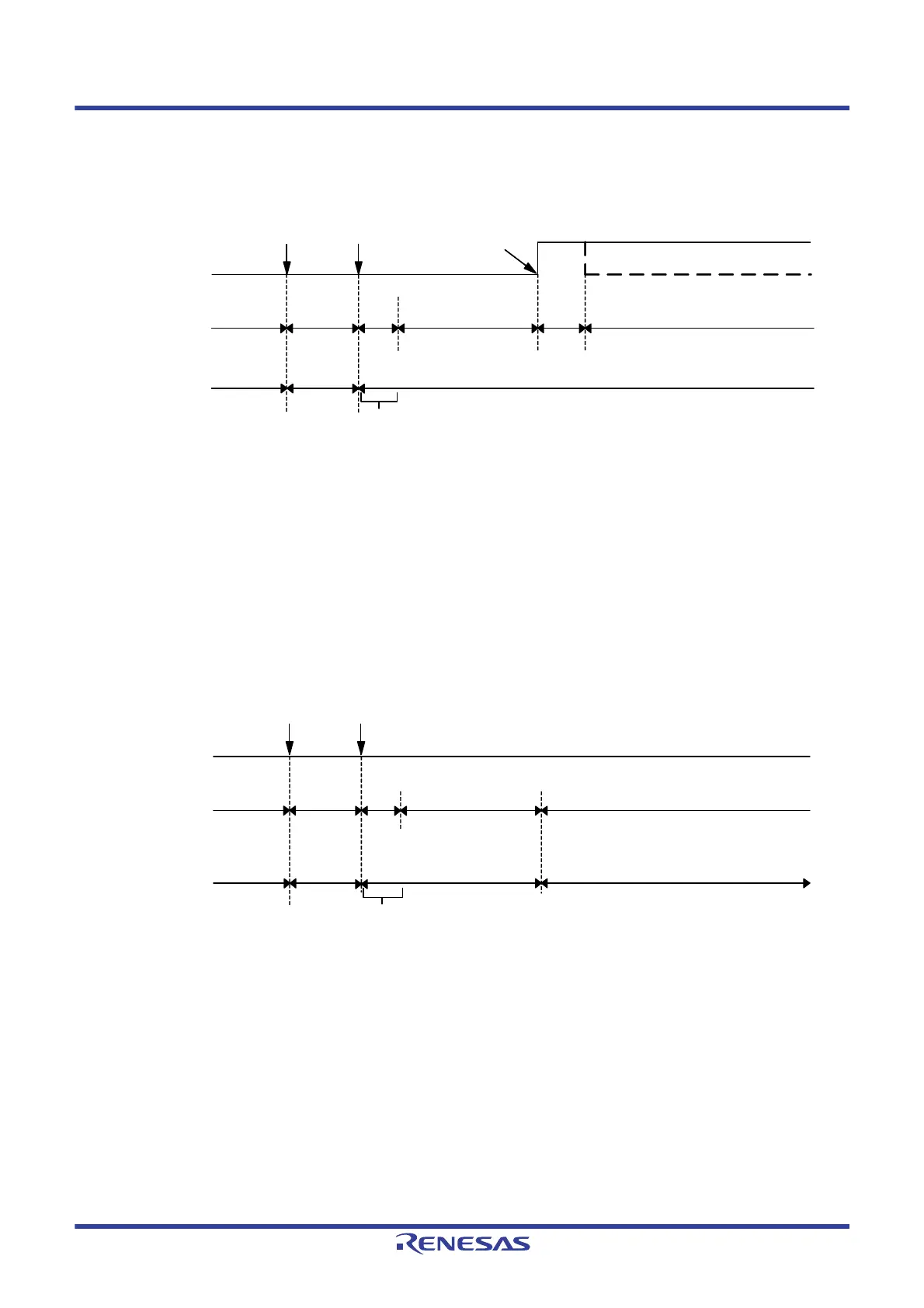
(2) Timing diagram when the interrupt request signal is generated in the SNOOZE mode
Figure 20 - 7 When the Interrupt Request Signal is Generated in the SNOOZE Mode
Note 1. For details of the standby release signal, see Figure 19 - 1.
Note 2. Transition time from STOP mode to SNOOZE mode
Note 3. Transition time from SNOOZE mode to normal operation
Note 4. Enable the SNOOZE mode (AWC = 1 or SWC = 1) immediately before switching to the STOP mode.
Note 5. Be sure to release the SNOOZE mode (AWC = 0 or SWC = 0) immediately after return to the normal operation.
(3) Timing diagram when the interrupt request signal is not generated in the SNOOZE mode
Figure 20 - 8 When the Interrupt Request Signal is not Generated in the SNOOZE Mode
Note 1. For details of the standby release signal, see Figure 19 - 1.
Note 2. Transition time from STOP mode to SNOOZE mode
Note 3. Enable the SNOOZE mode (AWC = 1 or SWC = 1) immediately before switching to the STOP mode.
Remark For details of the SNOOZE mode function, see CHAPTER 13 A/D CONVERTER.
H
L
Normal operation
Note 5
(high-speed on-chip oscillator clock)
Note 3
SNOOZE mode
(A/D conversion)
Note 2
STOP mode
Normal
operation
Note 4
(high-speed on-chip
oscillator clock)
Oscillates
Oscillation
stopped
Oscillates
Wait for oscillation accuracy stabilization
Status of CPU
High-speed
on-chip oscillator
clock
STOP
instruction
Trigger
detection
Interrupt request
Standby release
signal
Note 1
STOP
instruction
Trigger
detection
Wait for oscillation accuracy stabilization
L
STOP mode
(Waiting for a trigger to switch to the SNOOZE mode)
SNOOZE mode
(A/D conversion)
Note 2
Oscillation stoppedOscillates
Oscillates
Oscillation
stopped
STOP mode
Normal
operation
Note 3
(high-speed on-chip
oscillator clock)
Status of CPU
High-speed
on-chip oscillator
clock
Standby release
signal
Note 1
 Loading...


