RL78/G1H CHAPTER 31 ELECTRICAL SPECIFICATIONS
R01UH0575EJ0120 Rev. 1.20 Page 889 of 920
Dec 22, 2016
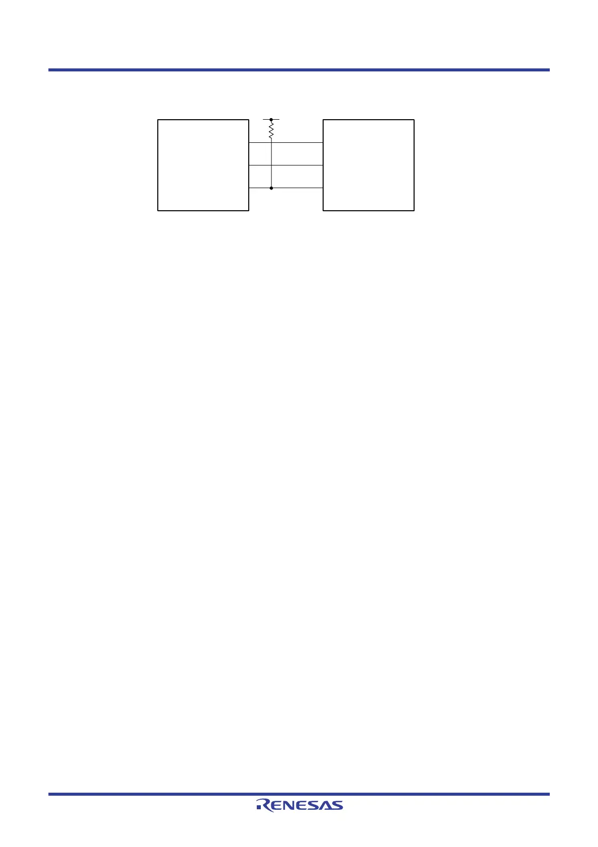
CSI mode connection diagram (during communication at different potential)
Remark 1. Rb[Ω]: Communication line (SOp) pull-up resistance, Cb[F]: Communication line (SOp) load
capacitance,
V
b[V]: Communication line voltage
Remark 2. p: CSI number (p = 10, 30), m: Unit number (m = 0, 1), n: Channel number (n = 2),
g: PIM and POM number (g = 0, 14)
Remark 3. fMCK: Serial array unit operation clock frequency
(Operation clock to be set by the CKSmn bit of serial mode register mn (SMRmn). m: Unit
number,
n: Channel number (mn = 02, 12))
Remark 4. CSI21 cannot communicate at different potential. Use other CSI for communication at different
potential.
SCKp
SOp
User’s device
SCK
SI
SIp SO
Vb
Rb
<Slave>
RL78 microcontroller
 Loading...


