EasyManua.ls Logo

Tektronix TBS2000 Series User Manual

Tektronix TBS2000 Series
328 pages
To Next Page IconTo Next Page
To Previous Page IconTo Previous Page
Page #51 background imageLoading...
Page #51 background image
Each data value requires two to seven characters. This includes one character
for the minus sign if the value is negative, one to five ASCII characters for
the waveform value, and a comma to separate data points.
An example of an ASCII waveform data string follows:
CURVE<space>-110,-109,-110,-110,-109,-107,-109,-107,
-106,-105,-103,-100,-97,-90,-84,-80
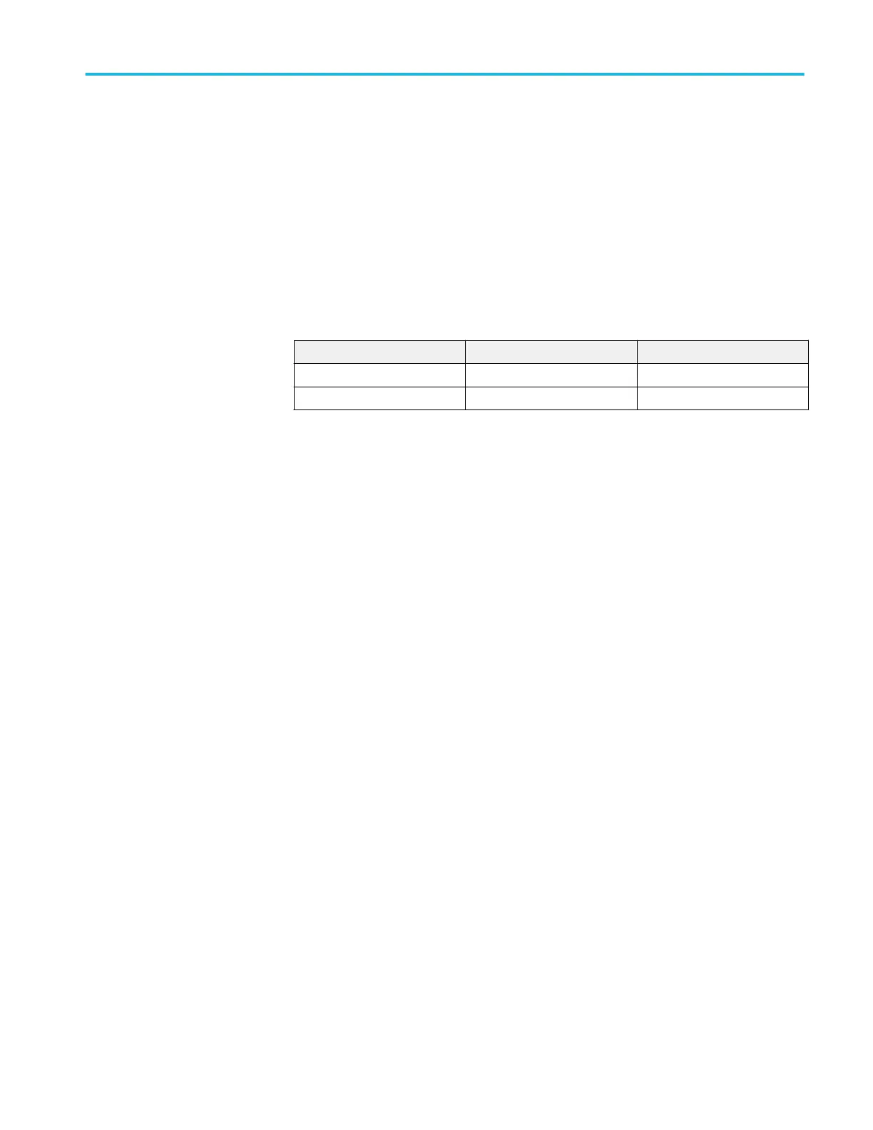
Binary data can be represented by signed integer or positive integer values.
The range of the values depends on the byte width specified.
Table 25: Binary data ranges
Byte width Signed integer range Positive integer range
1 -128 to 127 0 to 255
2 -32,768 to 32,767 0 to 65,535
The defined binary formats also specify the order in which the bytes are
transferred giving a total of four binary formats: RIBinary, RPBinary, SRIbinary,
and SRPbinary.
RIBinary is signed integer where the most significant byte is transferred first, and
RPBinary is positive integer where the most significant byte is transferred first.
SRIbinary and SRPbinary correspond to RIBinary and RPBinary respectively but
use a swapped byte order where the least significant byte is transferred first. The
byte order is ignored when DATa:WIDth is set to 1.
Waveform data record
You can transfer multiple points for each waveform record. You can transfer a
part of the waveform or you can transfer the entire record. The DATa:STARt and
DATa:STOP commands let you specify the first and last data points of the
waveform record.
When transferring data into the instrument you must specify the location of the
first data point within the waveform record. For example, when DATa:STARt is
set to 1, data points will be stored starting with the first point in the record, and
when DATa:STARt is set to 500, data will be stored starting at the 500th point in
the record. The instrument ignores DATa:STOP when reading in data as the
instrument will stop reading data when there is no more data to read or when it
has reached 2500 data points.
You must specify the first and last data points in the waveform record when
transferring data from the instrument to an external device. Setting DATa:STARt
to 1 and DATa:STOP to 2500 always sends the entire waveform, regardless of
the acquisition mode.
Command groups
TBS2000 Series Programmer 33

Table of Contents

Other manuals for Tektronix TBS2000 Series

Question and Answer IconNeed help?

Do you have a question about the Tektronix TBS2000 Series and is the answer not in the manual?

Tektronix TBS2000 Series Specifications

General IconGeneral
Bandwidth70 MHz, 100 MHz, 200 MHz
Channels2 or 4
Time Base Range5 ns/div to 50 s/div
Probe InterfaceTekVPI
Operating Temperature0 °C to +50 °C
Vertical Resolution8 bits
Sample Rate1 GS/s
Memory Depth20 kpts
Record Length20 kpts
Display9-inch WVGA display
Input Impedance1 MΩ ±1%, 13 pF ±2 pF
Vertical Sensitivity2 mV/div to 5 V/div
Trigger TypesEdge, Pulse Width, Video
ConnectivityUSB, LAN
Math FunctionsAddition, Subtraction, Multiplication, Division, FFT

Summary

Getting Started with TBS2000 Series Programmer

Remote Operation Overview

Provides information on remotely controlling the instrument via communication protocols and commands.

Understanding Command Syntax

Command and Query Structure

Explains the formation of set and query commands, including headers, mnemonics, and arguments.

BNF Notation

Details the Backus-Naur Form used for describing command syntax and structure.

Command Entry Rules

Outlines general rules for entering commands, including case sensitivity and whitespace.

Concatenating Commands

Explains how to combine multiple commands and queries using semicolons for sequential execution.

Organizing Commands into Groups

Acquisition Command Group

Manages waveform acquisition modes, settings, and averaging parameters.

Ethernet Command Group

Controls the instrument's Ethernet interface settings and operations.

Horizontal Command Group

Manages horizontal axis settings, time base, and record length.

Measurement Command Group

Configures and retrieves automated measurement results.

Trigger Command Group

Defines and manages instrument trigger conditions and settings.

Understanding Status and Events

Registers Overview

Explains the instrument's status and enable registers for event reporting.

Event Handling Sequence

Details the process of how the status and event handling system manages instrument events.

Related product manuals