Setting a Variable PCS
For advanced use cases, where the part is not grasped with high consistency, you can set
a Variable PCS to adjust the toolpath moves according to the part location and orientation
relative to the robot tool flange. You can create a pose variable tied to an external sensor
that can detect the PCS location and orientation.
1. Set up an external sensor that detects the PCS location and orientation. You must
convert the sensor output to the robot tool flange frame.
2. Verify the PCS is set up relative to the part and the location and orientation are
detectable by the external sensor.
3. In PolyScope, create a pose variable tied to the external sensor output as a variable
PCS. Give it a distinct name, for example, variable_rtcp_pcs_1.
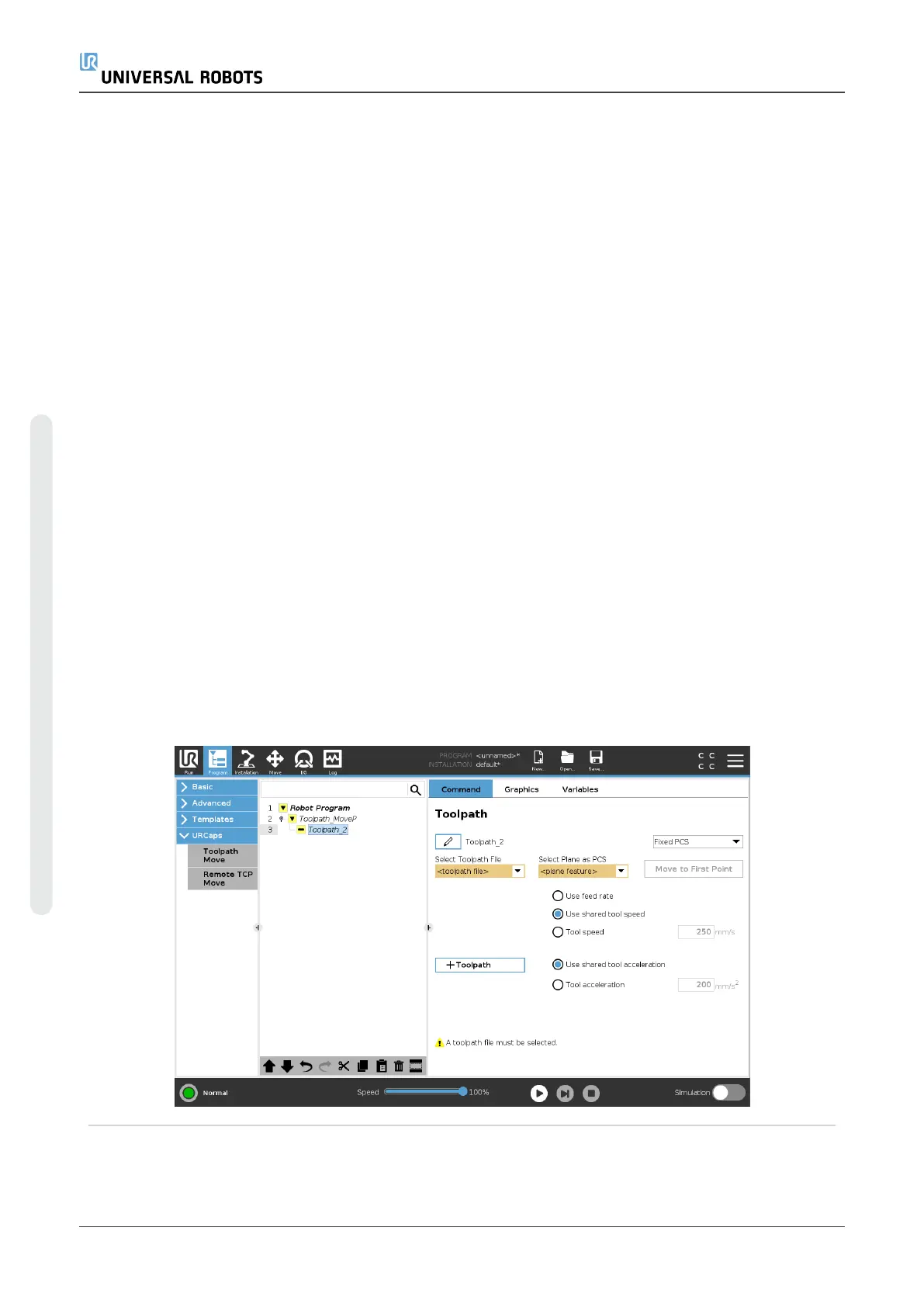
4. Insert an RTCP Toolpath Node.
5. At the top right corner of the program page, in the drop-down menu, select Variable
PCS.
6. In the Select PCS drop-down menu, select variable_rtcp_pcs_1.
7. Create an Assignment or Script node to update variable_rtcp_pcs_1 before the
RTCP Toolpath Node.
The following section explains how to use a variable PCS in a Remote TCP Toolpath
node.
Configuring a Remote TCP Toolpath Node
UR5e 200 User Manual
23.Program Tab
Copyright © 2009–2021 by UniversalRobotsA/S. All rights reserved.

 Loading...


