Configuring a Regular TCP
•
Follow the instructions in 24.2. TCP Configurationon page205 to configure a
Regular TCP.
•
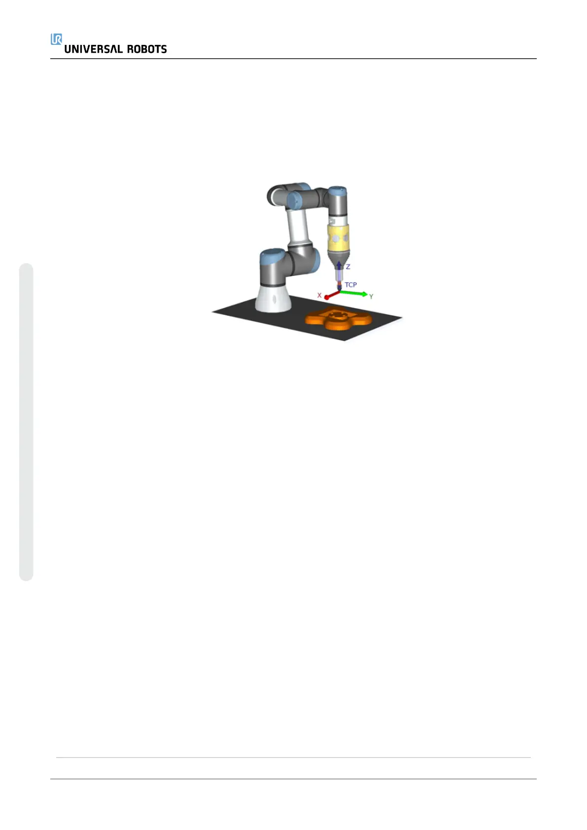
Verify the positive Z-axis of the tool points away from the part surface.
Configuring a Plane Feature PCS
1. Create a plane feature by Adding a plane or Teaching a plane. See 24.17.5. Plane
Featureon page227.
2. Fix the part relative to the robot base.
3. Verify the correct TCP is us to create the plane feature. For high accuracy,
temporarily set up a sharp Remote TCP to complete this teaching process.
4. Jog the robot for the Remote TCP to touch the origin, positive X-axis and the
positive Y-axis direction of the PCS on the part.
5. Finish the teaching process and confirm the PCS position and orientation.
Configuring a Toolpath Node
1. Access the Program Tab and tap URCaps.
2. Select a TCP and set the motion parameters: tool speed, tool acceleration and
blend radius. Select Spin tool freely around its Z-axis. Do not select if the tool must
follow the orientation around Z-axis defined in the toolpath file.
3. Tap +Toolpath to insert a Toolpath node.
4. In the drop-down menu, select a toolpath file and the corresponding PCS (Plane
Feature).
5. Adjust the motion parameters if different values are to be applied to the Toolpath
node.
UR5e 202 User Manual
23.Program Tab
Copyright © 2009–2021 by UniversalRobotsA/S. All rights reserved.

 Loading...


