•
Configure the Position to be the tip of the screwdriver tool where it contacts the screw.
•
Configure the Orientation so that the positive Z direction is aligned to the length of the
screws to be tightened.
You can visualize the X, Y and Z coordinates of the selected TCP to confirm it matches the
tool’s bit or socket.
The Screwdriving program node (see23.13.8. Screwdrivingon page191) uses the positive Z
direction of the selected TCP to follow the screw and calculate distances.
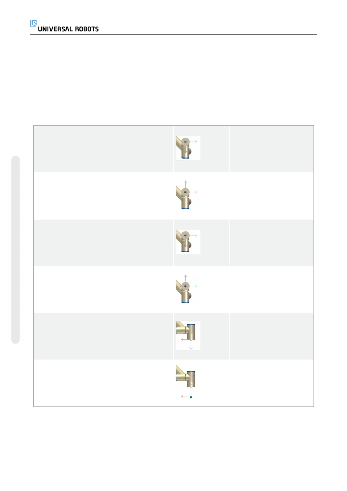
Typical Orientation values (in Rotation Vector [rad] notation) are illustrated in the following table.
Screwdriving axis parallel to the negative Y
direction of the robot’s tool flange
Orientation
•
RX: 1.5708 rad
•
RY: 0.0000 rad
•
RZ: 0.0000 rad
Screwdriving axis parallel to the positive Y
direction of the robot’s tool flange
Orientation
•
RX: -1.5708 rad
•
RY: 0.0000 rad
•
RZ: 0.0000 rad
Screwdriving axis parallel to the positive X
direction of the robot’s tool flange
Orientation
•
RX: 0.0000 rad
•
RY: 1.5708 rad
•
RZ: 0.0000 rad
Screwdriving axis parallel to the negative X
direction of the robot’s tool flange
Orientation
•
RX: 0.0000 rad
•
RY: -1.5708 rad
•
RZ: 0.0000 rad
Screwdriving axis parallel to the positive Z
direction of the robot’s tool flange
Orientation
•
RX: 0.0000 rad
•
RY: 0.0000 rad
•
RZ: 0.0000 rad
Screwdriving axis parallel to the negative Z
direction of the robot’s tool flange
Orientation
•
RX: 3.1416 rad
•
RY: 0.0000 rad
•
RZ: 0.0000 rad
UR5e 222 User Manual
24.Installation Tab
Copyright © 2009–2021 by UniversalRobotsA/S. All rights reserved.

 Loading...


