Default safety configuration
The robot is delivered with a default configuration, which enables operation without any
additional safety equipment (see illustration below).
24V
EI1
24V
SI0
24V
SI1
24V
EI0
Safety
Safeguard Stop
Emergency Stop
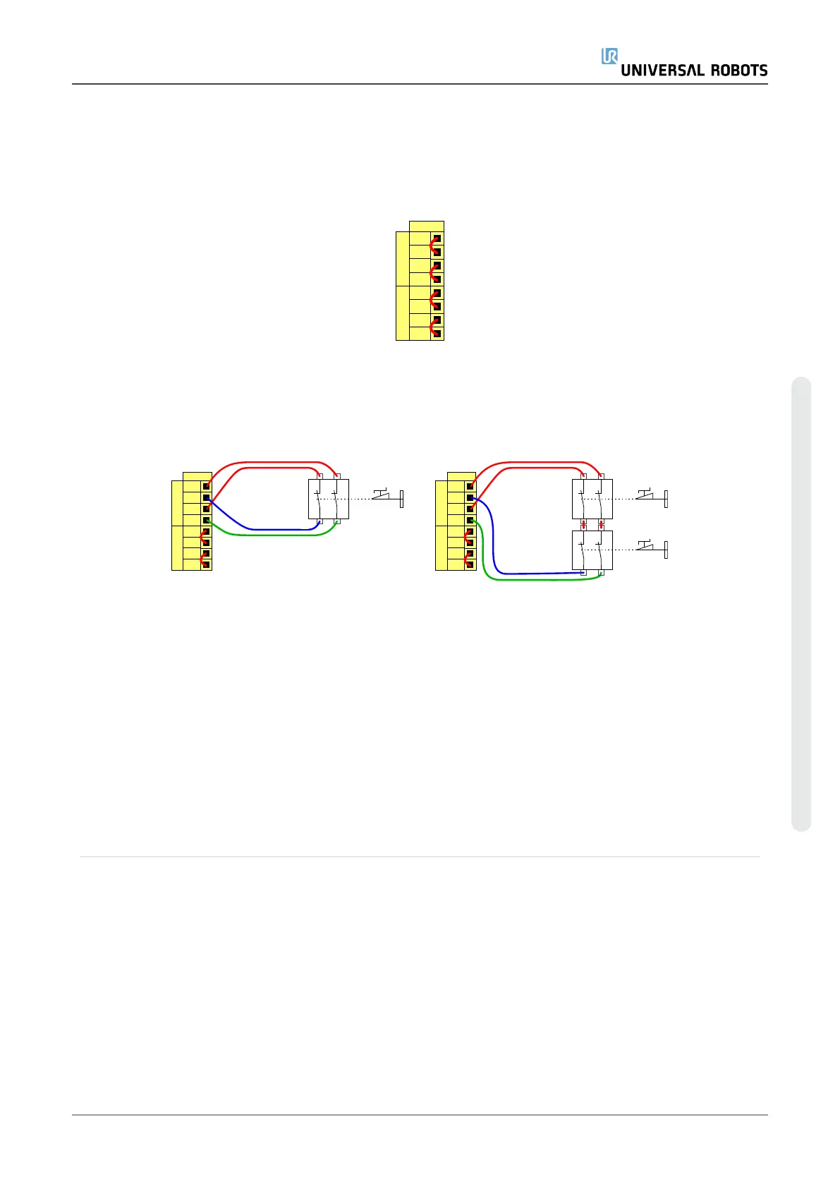
Connecting emergency stop buttons
Most applications require one or more extra emergency stop buttons. The illustration
below shows how one or more emergency stop buttons can be connected.
24V
EI1
24V
SI0
24V
SI1
24V
EI0
Safety
Safeguard Stop
Emergency Stop
24V
EI1
24V
SI0
24V
SI1
24V
EI0
Safety
Safeguard Stop
Emergency Stop
Sharing the Emergency Stop with other machines
You can set up a shared emergency stop function between the robot and other machines
by configuring the following I/O functions via the GUI. The Robot Emergency Stop Input
cannot be used for sharing purposes. If more than two UR robots or other machines need
to be connected, a safety PLC must be used to control the emergency stop signals.
•
Configurable input pair: External emergency stop.
•
Configurable output pair: System emergency stop.
The illustration below shows how two UR robots share their emergency stop functions. In
this example the configured I/Os used are CI0-CI1 and CO0-CO1.
User Manual 39 UR5e
6.Electrical Interface
Copyright © 2009–2021 by UniversalRobotsA/S. All rights reserved.

 Loading...


