4.3 The Drive and Programming Modes
YASKAWA ELECTRIC SIEP C710616 27G YASKAWA AC Drive A1000 Technical Manual 107
Start-Up Programming
& Operation
4
Simplified Setup Using the Setup Group
In the Setup Group, the drive lists the basic parameters needed to set up the drive for the application. It provides a
simplified way to get the application running right away by showing only the most important parameters.
Using the Setup Group
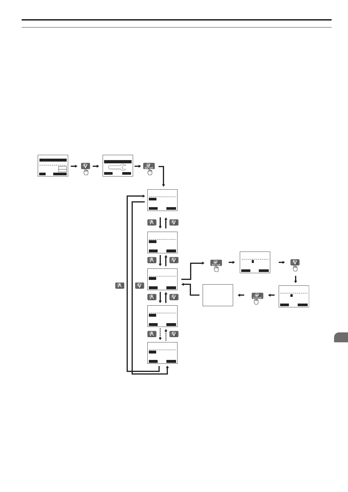
Figure 4.7 illustrates how to enter and how to change parameters in the Setup Group.
The first display shown when
entering the Setup Group is the Application Selection menu. Skipping this display will
keep the current Setup Group parameter selection. The default setting for the Setup Group is a group of parameters most
commonly use in general-purpose applications. Pressing the ENTER key from the Application Selection display and
selecting an Application Preset will change the Setup Group to parameters optimal for the application selected. Refer to
Application Selection on page 114 and Setup Group Parameters on page 108 for details.
In this example, the Setup Group is accessed to change b1-01
from 1 to 0. This changes the source of the frequency
reference from the control circuit terminals to the digital operator.
Figure 4.7 Setup Group Example
<1> Use the up and down arrow keys to scroll through the Setup Group. Press the ENTER key to view or change parameter settings.
<2> To return to the previous menu without saving changes, press the ESC key.
←
→
←
→
Control Circuit
Terminal
Parameter Display
Operator
<1>
<2>
<2>
Frequency reference
appears when
powered up
- MODE -
U1-01= 0.00Hz
U1-02= 0.00Hz
U1-03= 0.00A
DRV
FREF (OPR)
Rdy
JOG FWD FWD/REV
LSEQ
LREF
HELP
- MODE - PRG
Quick Setting
DATA
FWD
Entry Accepted
- SETUP -
b1-01= 1 ∗1∗
Analog Input
PRG
Ref Source 1
Rdy
Home FWD DATA
- SETUP -
A1-06= 0
∗0∗
General
PRG
Application Sel
Rdy
Home FWD DATA
- SETUP -
A1-02= 2
∗2∗
Open Loop Vector
PRG
Control Method
Rdy
Home FWD DATA
- SETUP -
b1-02= 1
∗1∗
Digital Inputs
PRG
Run Source 1
Rdy
Home FWD DATA
- SETUP -
L3-04= 1
∗1∗
General Purpose
PRG
StallP Decel Sel
Rdy
Home FWD DATA
“1”
- SETUP -
b1-01= 1
∗1∗
Analog Input
PRG
Ref Source 1
Rdy
FWD
“1”
- SETUP -
b1-01= 0
∗1∗
Operator
PRG
Ref Source 1
Rdy
FWD