3.9 Control Circuit Wiring
YASKAWA ELECTRIC SIEP C710616 27G YASKAWA AC Drive A1000 Technical Manual 87
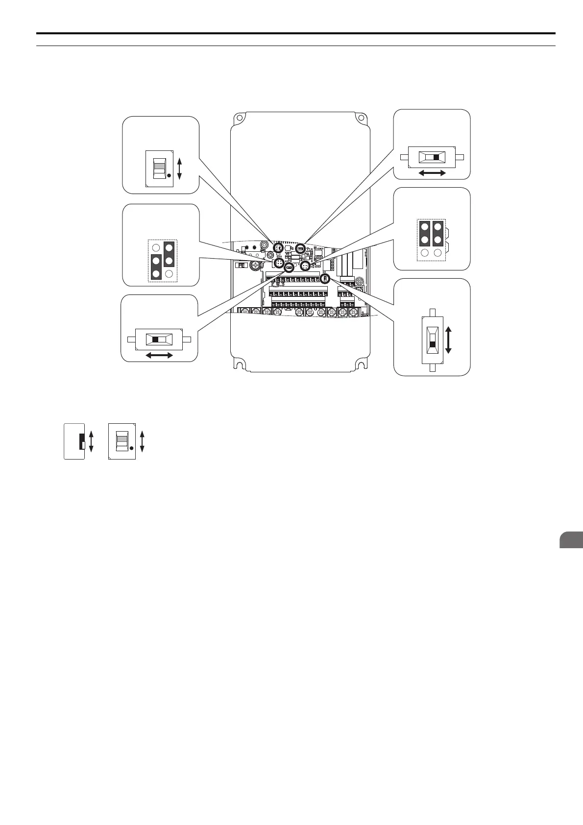
Switches and Jumpers on the Terminal Board
The terminal board is equipped with several switches used to adapt the drive I/Os to the external control signals.
Figure 3.27 shows the location of these switches. Refer to Control I/O Connections on page 88 for setting instructions.
Figure 3.30
Figure 3.27 Locations of Jumpers and Switches on the Terminal Board
<1> Available slide switch S6 is models ETC740310 and ETC740311.
MA MB MC
M1 M2 M5
M3 M6 M4
E(G)
HC H1 H2 DM+ DM- IG R+ R- S+ S-
S1 S2 S3 S4 S5 S6 S7 S8 SN SC SP
V+ AC V- A1 A2 A3 FM AM AC MP RP AC
VI
DIP Switch S1
Terminal A2 Signal
Selection
PTC
AI
DIP Switch S4
Terminal A3 Analog/
PTC Input Sel.
AMFM
V
I
Jumper S5
Terminal AM/FM Signal
Selection
Jumper S3
Terminal H1/H2
Sink/Source Sel.
DIP Switch S2
RS-422/485 Termination
Resistor
Off On
Slide Switch S6
Terminal DM+,DM-
N.C./N.O. Selection
N.C.
N.O.
<1>
N.C.
N.O.
ETC740310 ETC740311
N.C.
N.O.