B.3 Parameter Table
YASKAWA ELECTRIC SIEP C710616 27G YASKAWA AC Drive A1000 Technical Manual 469
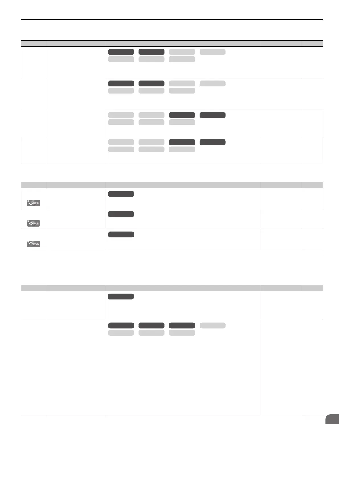
d6: Field Weakening and Field Forcing
d7: Offset Frequency
E: Motor Parameters
E1: V/f Pattern for Motor 1
No.(Addr.) Name Description Setting Page
d6-01
(2A0H)
Field Weakening Level
Sets the drive output voltage for the Field Weakening function as a percentage of the maximum
output voltage.
Enabled when a multi-function input is set for Field Weakening (H1- = 63).
Default: 80%
Min: 0%
Max: 100%
210
d6-02
(2A1H)
Field Weakening Frequency Limit
Sets the lower limit of the frequency range where Field Weakening control is valid.
The Field Weakening command is valid only at frequencies above this setting and only when
the output frequency matches the frequency reference (speed agree).
Default: 0.0 Hz
Min: 0.0 Hz
Max: 400.0 Hz
210
d6-03
(2A2H)
Field Forcing Selection
0: Disabled
1: Enabled
Default: 0
Min: 0
Max: 1
211
d6-06
(2A5H)
Field Forcing Limit
Sets the upper limit of the excitation current command during magnetic field forcing. A setting
of 100% is equal to motor no-load current. Disabled only during DC Injection Braking.
Default: 400%
Min: 100%
Max: 400%
211
No.(Addr.) Name Description Setting Page
d7-01
(2B2H)
Offset Frequency 1
Added to the frequency reference when the digital input “Frequency offset 1” (H1- = 44) is
switched on. A setting of 100% is equal to the drive maximum output current.
Default: 0.0%
Min: -100.0%
Max: 100.0%
211
d7-02
(2B3H)
Offset Frequency 2
Added to the frequency reference when the digital input “Frequency offset 2” (H1- = 45) is
switched on. A setting of 100% is equal to the drive maximum output current.
Default: 0.0%
Min: -100.0%
Max: 100.0%
211
d7-03
(2B4H)
Offset Frequency 3
Added to the frequency reference when the digital input “Frequency offset 3” (H1- = 46) is
switched on. A setting of 100% is equal to the drive maximum output current.
Default: 0.0%
Min: -100.0%
Max: 100.0%
211
No.(Addr.) Name Description Setting Page
E1-01
(300H)
Input Voltage Setting
This parameter must be set to the power supply voltage.
WARNING! Drive input voltage (not motor voltage) must be set in E1-01 for the protective
features of the drive to function properly. Failure to do so may result in equipment damage and/
or death or personal injury.
Default: 200 V
<18>
Min: 155 V
Max: 255 V
212
E1-03
(302H)
V/f Pattern Selection
0: 50 Hz, Constant torque 1
1: 60 Hz, Constant torque 2
2: 60 Hz, Constant torque 3 (50 Hz base)
3: 72 Hz, Constant torque 4 (60 Hz base)
4: 50 Hz, Variable torque 1
5: 50 Hz, Variable torque 2
6: 60 Hz, Variable torque 3
7: 60 Hz, Variable torque 4
8: 50 Hz, High starting torque 1
9: 50 Hz, High starting torque 2
A: 60 Hz, High starting torque 3
B: 60 Hz, High starting torque 4
C: 90 Hz (60 Hz base)
D: 120 Hz (60 Hz base)
E: 180 Hz (60 Hz base)
F: Custom V/f, E1-04 through E1-13 settings define the V/f pattern
Note: Setting F is only available in vector control modes.
Default: F
<3>
Min: 0
Max: F
212
OLV/PM AOLV/PM
CLV
V/f w/PG
CLV/PM
V/f OLV
OLV/PM AOLV/PM
CLV
V/f w/PG
CLV/PM
V/f OLV
OLV/PM AOLV/PM
CLV
V/f w/PG
CLV/PM
V/f OLV
OLV/PM AOLV/PM
CLV
V/f w/PG
CLV/PM
V/f OLV
All Modes
All Modes
OLV/PM AOLV/PM
CLV
V/f w/PG
CLV/PM
V/f OLV