3.8 Main Circuit Wiring
YASKAWA ELECTRIC SIEP C710616 27G YASKAWA AC Drive A1000 Technical Manual 81
Note: When connecting peripheral devices and options to the terminals –, +1, +3, B1, and B2, refer to the instruction manuals for each
devices. For more information, contact YASKAWA or your nearest sales representative.
Main Circuit Terminal and Motor Wiring
This section outlines the various steps, precautions, and checkpoints for wiring the main circuit terminals and motor
terminals.
NOTICE: When connecting the motor to the drive output terminals U/T1, V/T2, and W/T3, the phase order for the drive and motor
should match. Failure to comply with proper wiring practices may cause the motor to run in reverse if the phase order is backward.
NOTICE: Do not connect phase-advancing capacitors or LC/RC noise filters to the output circuits. Failure to comply could result in
damage to the drive, phase-advancing capacitors, LC/RC noise filters or ground fault circuit interrupters.
NOTICE: Do not connect the AC power line to the output terminals of the drive. Failure to comply could result in death or serious injury
by fire as a result of drive damage from line voltage application to output terminals.
Cable Length Between Drive and Motor
Voltage drop along the motor cable may cause reduced motor torque when the wiring between the drive and the motor is
too long, especially at low frequency output. This can also be a problem when motors are connected in parallel with a
fairly long motor cable. Drive output current will increase as the leakage current from the cable increases. An increase in
leakage current may trigger an overcurrent situation and weaken the accuracy of the current detection.
Adjust the drive carrier frequency according to Table 3.6. If the motor wiring distance excee
ds 100 m because of the
system configuration, reduce the ground currents. Refer to C6-02: Carrier Frequency Selection on page 196.
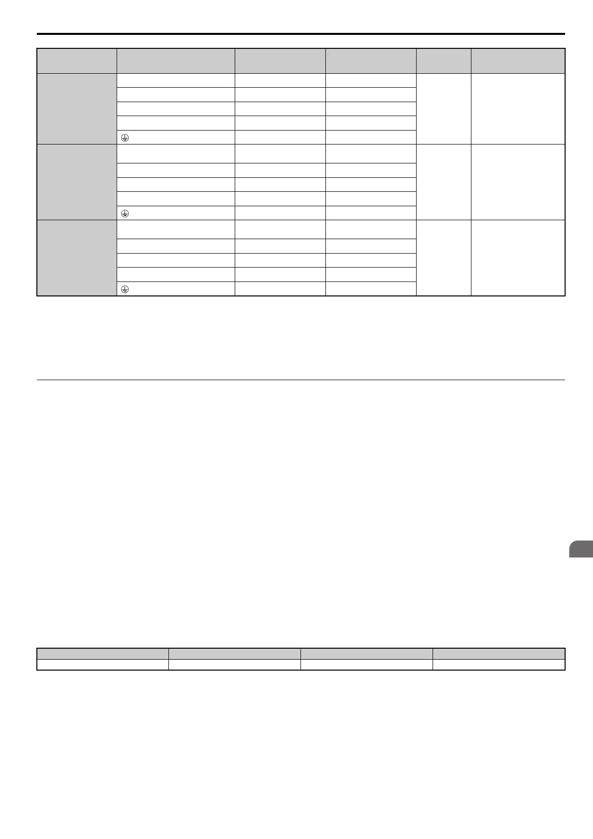
Table 3.6 Cable Length Between Drive and Motor
Note: 1. When setting carrier frequency in a drive running multiple motors, calculate the cable length as the total distance of wiring to all
motors that are connected.
2. The maximum cable length is 100 m when using OL
V/PM (A1-02 = 5) or AOLV/PM (A1-02 = 6).
4A0675
R/L1, S/L2, T/L3 95 4P 95 to 150
M12
32 to 40
(28
3 to 354)
U/T1, V/T2, W/T3 95 4P 95 to 150
–, +1 – 70 to 150
+3 – 70 to 150
95 2P 60 to 150
4A0930
R/L1, S/L2, T/L3, R1/L11, S1/L21, T1/
L31
120 4P 95 to 150
M12
32 to 40
(283 to 354)
U/T1, V/T2, W/T3 120 4P 95 to 150
–, +1 – 95 to 150
+3 – 95 to 150
120 2P 70 to 120
4A1200
R/L1, S/L2, T/L3, R1/L11, S1/L21, T1/
L31
(95 4P)
2 95 to 150
M12
32 to 40
(28
3 to 354)
U/T1, V/T2, W/T3 (95 4P)
2 95 to 150
–, +1 – 120 to 150
+3 – 95 to 150
95 4P 95 to 120
<1> When using the wire of this gauge in accordance with IEC/EN 61800-5-1, install an equipment for residual current monitoring/detection
(RCM/RCD).
<2> When using the wire of this gauge in accordance with IEC/EN 61800-5-1, install an equipment for residual current monitoring/detection
(RCM/RCD), or use copper wire of 10 mm
2
(AWG 8).
Cable Length 50 m or less 100 m or less Greater than 100 m
Carrier Frequency 15 kHz or less 5 kHz or less 2 kHz or less
Model
CIMR-A
Terminal
Recomm. Gauge
mm
2
Applicable
Gauge
mm
2
Screw
Size
Tightening
Torque
Nm (lb.in.)