D.3 UL Standards
596 YASKAWA ELECTRIC SIEP C710616 27G YASKAWA AC Drive A1000 Technical Manual
Wiring Fuses for Models 4A0930 and 4A1200
NOTICE: If a fuse is blown or equipment for residual current monitoring/detection (RCM/RCD) is tripped, check the wiring and the
selection of the peripheral devices to identify the cause. Contact YASKAWA before restarting the drive or the peripheral devices if the
cause cannot be identified.
Install a fuse on the input side to protect drive wiring and prevent other secondary damage. Wire the fuse so that leakage
current in the upper controller power supply will trigger the fuse and shut off the power supply.
Select the appropriate fuse from Table D.10.
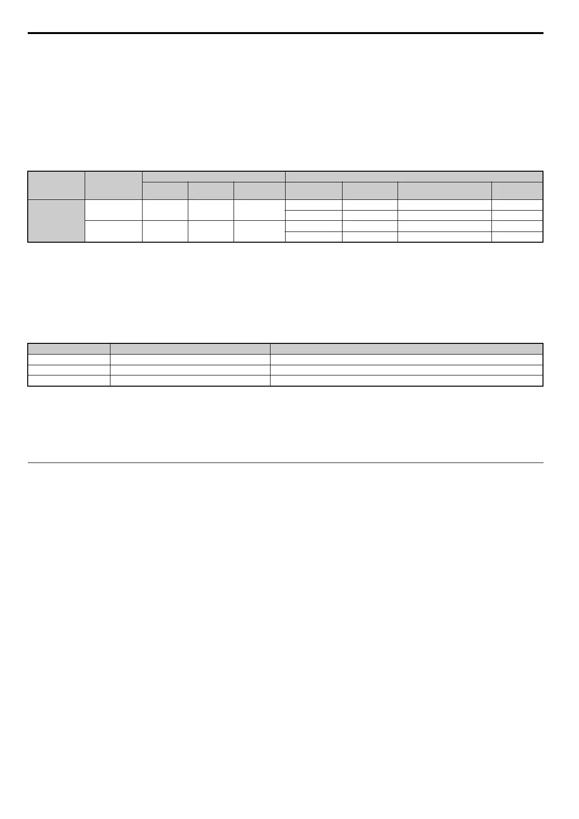
Table D.10 Input Fuses for Models 4A0930 and 4A1200
Low Voltage Wiring for Control Circuit Terminals
Wire low voltage wires with NEC Class 1 circuit conductors. Refer to national state or local codes for wiring. If external
power supply used, it shall be UL Listed Class 2 power source only or equivalent. Refer to NEC Article 725 Class 1,
Class 2, and Class 3 Remote-Control, Signaling, and Power Limited Circuits for requirements concerning class 1 circuit
conductors and class 2 power supplies.
Table D.11 Control Circuit Terminal Power Supply
Drive Short-Circuit Rating
This drive is suitable for use on a circuit capable of delivering not more than 100,000 RMS symmetrical amperes, 600 V
ac maximum (Up to 240 V in 200 V class drives, up to 480 V for 400 V class drives), when protected by Bussmann Type
FWH fuses as specified in Table D.8.
Drive Motor Overload Protection
Set parameter E2-01 (motor rated current) to the appropriate value to enable motor overload protection. The internal
motor overload protection is UL Listed and in accordance with the NEC and CEC.
E2-01 Motor Rated Current
Setting Range: Model Dependent
Default Setting: Model Dependent
Parameter E2-01 (motor rated current) protects t
he motor if parameter L1-01 is not set to 0 (default is 1, enabling
protection for standard induction motors).
If Auto-Tuning has been performed successful
ly, the motor data entered to T1-04 is automatically written into parameter
E2-01. If Auto-Tuning has not been performed, manually enter the correct motor rated current to parameter E2-01.
Voltage Class Model
Selection Input Fuse (Example)
Input Voltage
(V)
Current (A)
Pre-arc
I
2
t (A
2
s)
Model Manufacturer Rating
Pre-arc
I
2
t (A
2
s)
Three-Phase
400 V Class
4A0930 480 1500
140000 to
31
00000
CS5F-1200 Fuji Electric AC500 V, 1200 A 276000
FWH-1200A Bussmann AC500 V, 1200 A –
4A1200 480 1500
320000 to
31
00000
CS5F-1500 Fuji Electric AC500 V, 1500 A 351000
FWH-1600A Bussmann AC500 V, 1600 A –
Input/Output Terminal Signal Power Supply Specifications
Open Collector Outputs DM+, DM- Requires class 2 power supply.
Digital inputs S1-S8, SN, SC, SP, HC, H1, H2 Use the internal LVLC power supply of the drive. Use class 2 for external power supply.
Analog inputs/outputs +V, -V, A1, A2, A3, AC, AM, FM Use the internal LVLC power supply of the drive. Use class 2 for external power supply.