4.3 The Drive and Programming Modes
108 YASKAWA ELECTRIC SIEP C710616 27G YASKAWA AC Drive A1000 Technical Manual
Setup Group Parameters
Table 4.4 lists parameters available by default in the Setup Group. When an Application Preset has been selected in
parameter A1-06 or the Application Selection display of
the Setup Group, the parameters selected for the Setup Group
will change automatically. Refer to Application Selectio
n on page 114.
If the desired parameter is not listed in the Setup Group,
go to the Programming Mode.
Table 4.4 Setup Group Parameters
Note: 1. Parameter availability depends on the control mode set in A1-02 that is used to run the drive and motor. Consequently, some of the
parameters listed above may not be accessible in certain control modes.
2. Parameters listed in Table 4.4 are set in alphanumeric order
as User Parameters in A2-01 to A2-26.
Switching Between LOCAL and REMOTE
When the drive is set to accept the Run command from the digital operator RUN key, this is referred to as LOCAL mode.
When the drive is set to accept the Run command from an external device (via the input terminals, serial
communications, etc.) this is referred to as REMOTE mode.
WARNING! Sudden Movement Hazard. The drive may start unexpectedly if the Run command is already applied when switching from
LOCAL mode to REMOTE mode when b1-07 = 1, resulting in death or serious injury. Be sure all personnel are clear of rotating
machinery.
The operation can be switched between LOCAL and REMOTE either by using the LO/RE key on the digital operator or
a digital input.
Note: 1. After selecting LOCAL, the LO/RE light will remain lit.
2. The drive
will not allow the user to switch between LOCAL and REMOTE during run.
Using the LO/RE Key on the Digital Operator
Using Input Terminals S1 through S8 to Switch between LO/RE
The user can also switch between LOCAL and REMOTE modes using one of the digital input terminals S1 through S8
(set the corresponding parameter H1- to “1”).
Setting H1- to 1 disables the LO/RE key on the digital operator. Refer to H1: Multi-Function Digital Inputs on
page 482 for details.
Parameter Name Parameter Name
A1-02 Control Method Selection E1-01 Input Voltage Setting
b1-01 Frequency Reference Selecti
on 1 E1-03 V/f Pattern Selection
b1-02 Run Command Selection 1 E1-04 Maximum Output Frequency
b1-03 Stopping Method Selection E1-05 Maximum Voltage
C1-01 Acceleration Time 1 E1-06 Base Frequency
C1-02 Deceleration Time 1 E1-09 Minimum Output Frequency
C6-01 Drive Duty Mode Selection E1-13 Base Voltage
C6-02 Carrier Frequency Selection E2-01 Motor Rated Current
d1-01 Frequency Refe
rence 1 E2-04 Number of Motor Poles
d1-02 Frequency Refe
rence 2 E2-11 Motor Rate Power
d1-03 Frequency Refe
rence 3 H4-02 Multi-Function Analog Output Terminal FM Gain
d1-04 Frequency Refe
rence 4 L1-01 Motor Overload Protection Function Selection
d1-17 Jog Frequency Reference L3-04
Stall Prevention Selection during Deceleration
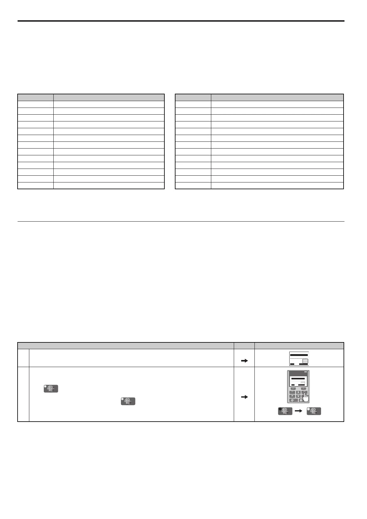
Step Display/Result
1. Turn on the power to the drive. The initial display appears.
2.
Press . The LO/RE light will light up. The drive is now in LOCAL.
To set the drive for REMOTE operation, press the key again.
- MODE -
U1-01= 0.00Hz
U1-02= 0.00Hz
U1-03= 0.00A
DRV
FREF (A1/A2)
Rdy
JOG FWD FWD/REV
RSEQ
RREF
LO
RE
F2F1
ESC
RUN STOP
ENTERRESET
ALM
DIGITAL OPERATOR JVOP-180
- MODE -
U1-01= 0.00Hz
U1-02= 0.00Hz
U1-03= 0.00A
DRV
FREF (OPR)
Rdy
JOG FWD FWD/REV
LSEQ
LREF