2.2 Mechanical Installation
48 YASKAWA ELECTRIC SIEP C710616 27G YASKAWA AC Drive A1000 Technical Manual
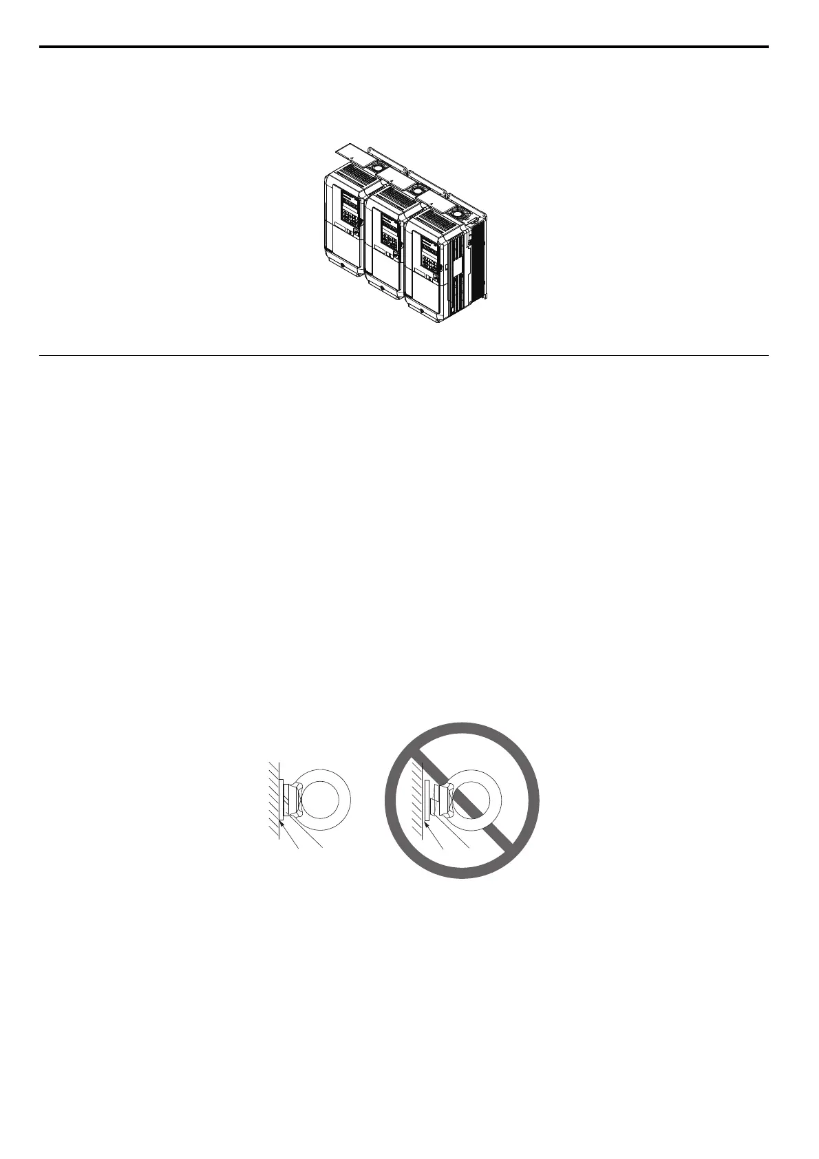
When drives with IP20/NEMA 1, UL Type 1 enclosures are mounted side by side, the top protective covers of all drives
must be removed as shown in Figure 2.4. Refer to Top Protective Cover on page 74 to remove and reattach the top
protective cover.
Figure 2.4
Figure 2.4 IP20/NEMA 1, UL Type 1 Side-by-Side Mounting in Enclosure
Instructions on Installation
Eye bolts are used to install the drive or to temporarily lift the drive when replacing it. The drive can be installed in an
enclosure panel or on a wall. Do not leave the drive suspended by the wires in a horizontal or vertical position for long
periods of time. Do not transport the drive over long distances. Read the following precautions and instructions before
installing the drives.
WARNING! Be sure to observe the following instructions and precautions. Failure to comply could result in minor or moderate injury
and damage to the drive from falling equipment.
• Before using wires to suspend the drive vertically and horizontally, make sure that the drive front cover,
terminal blocks and other drive components are securely fixed with screws.
• Do not subject the drive to vibration or impact greater than 1.96 m/s
2
(0.2 G) while it is suspended by the
wires.
• Do not overturn the drive while it is suspended by the wires.
• Do not leave the drive suspended by the wires for long periods of time.
Horizontal Suspension of the Drive (CIMR-A2A0360, 2A0415, 4A0250 to 4A0675)
To make a wire hanger or frame for use when lifting the drive with a crane, lay the drive in a horizontal position and pass
a wire through the holes of the four eye bolts.
When lifting the drive, confirm that the spring washer is full
y closed. If not, the drive may become deformed or damaged
when lifted.
Figure 2.5
Figure 2.5 Details of Spring Washers
A – No space between drive and washer C – Space between drive and washer
B – Spring washer: Fully closed D – Spring washer: Open