5.5 E: Motor Parameters
216 YASKAWA ELECTRIC SIEP C710616 27G YASKAWA AC Drive A1000 Technical Manual
V/f Pattern Settings E1-04 to E1-13
Set E1-03 E to monitor, but not change, the V/f pattern using parameters E1-04 to E1-13. To create a new V/f pattern,
set E1-03 to F. Refer to Figure 5.56 for an example custom V/f pattern.
Note: Certain E1- parameters might not be visible depending on the selected control mode. Refer to Parameter Table on page 453
for details.
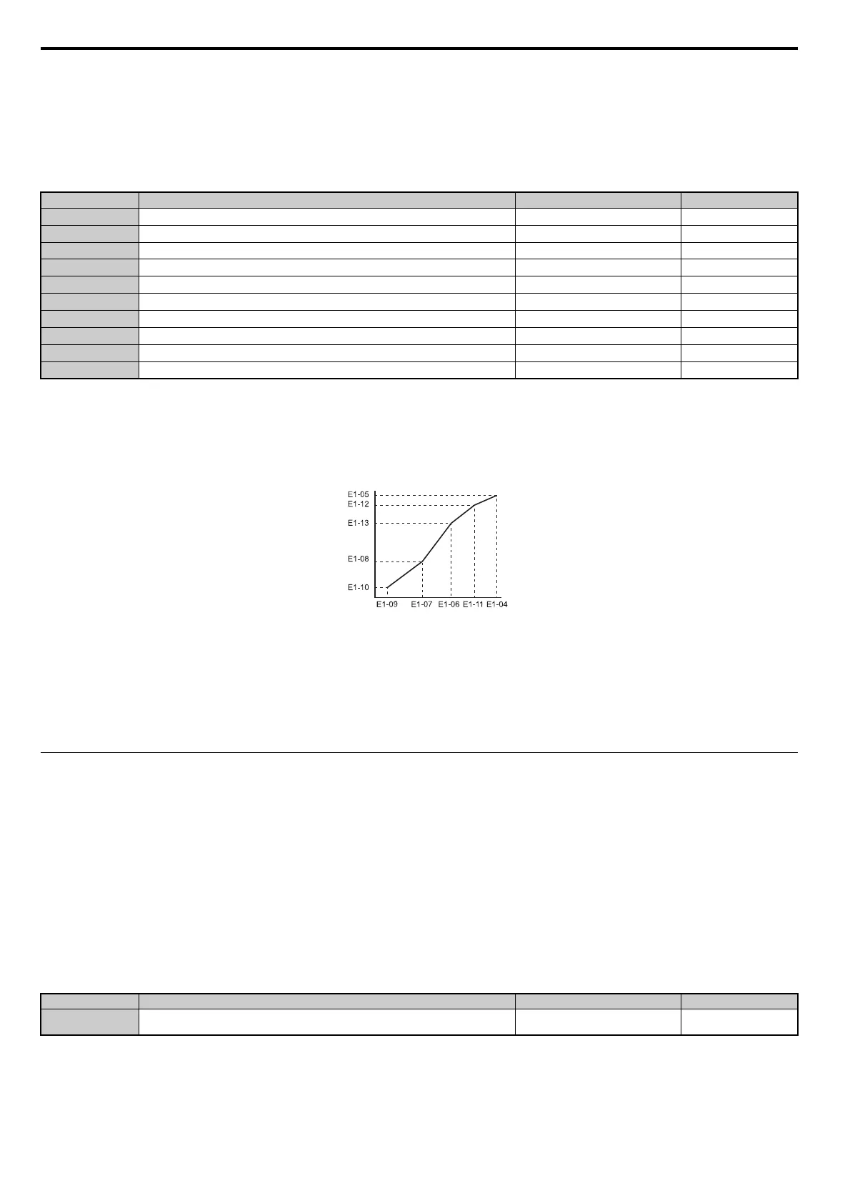
Figure 5.56
Figure 5.56 V/f Pattern
Note: 1. The
following condition must be true when setting up the V/f pattern: E1-09 E1-07 E1-06 E1-11 E1-04
2. T
o make the V/f pattern a straight line below E1-06, set E1-09 = E1-07. In this case the E1-08 setting is disregarded.
3. E1-03 is unaffected when the parameters are initialized using parameter A1-03, but the settings for E1-04 through E1-13 are returned
to their default values.
4. Parameters
E1-11, E1-12, and E1-13 should only be used to fine-tune the V/f pattern in the constant output range. These parameters
rarely need to be changed.
E2: Motor 1 Parameters
These parameters contain the motor data needed for motor 1. They are set automatically when Auto-Tuning is performed
(this includes Rotational Auto-Tuning, Stationary Auto-Tuning 1 and 2). If Auto-Tuning cannot be performed, refer to
Auto-Tuning Fault Detection on page 360 for detail.
Note: As the motor parameters for a PM motor are set up in the E5- parameters, parameters for induction motors (E2-) are
hidden when a PM motor control mode is selected for motor 1 (i.e., parameter A1-02 is set to 5, 6, or 7).
E2-01: Motor Rated Current
Provides motor control, protects the motor, and calculates torque limits. Set E2-01 to the full load amps (FLA) stamped
on the motor nameplate. If Auto-Tuning completes successfully, the value entered to T1-04 will automatically be saved
to E2-01.
Note: 1. Display is in the following units.
CIMR-A2A0004 to 2A0040, CIMR-A4A0002 to 4A0023: 0.01 A units
CIMR-A2A0056 to 2A0312, CIMR-A4A0031 to 4A0675: 0.1 A units
CIMR-A4A0930 to 4A1200: 1 A units
2. An oPE02 error will occur if E2-01 E2-03
. Set E2-03 correctly to prevent this error.
No.
<1> Default setting is determined by E5-01 in OLV/PM. The setting range is 0.0 to 400.0 Hz when E5-01 = FFFF.
<2> Default setting is determined by the Drive Model, Control Method, and Drive Duty.
<3> When using PM motors, the default setting is determined by the motor code set to E5-01.
<4> Values shown here are for 200 V class drives. Double values when using a 400 V class unit.
<5> Parameter ignored when E1-11 and E1-12 are set to 0.0.
<6> When Auto-Tuning is performed, E1-13 and E1-05 will be set to the same value.
Parameter Name Setting Range Default
E1-04
Maximum Output Frequency
40.0 to 400.0 Hz <1> <2> <3>
E1-05
Maximum Voltage
0.0 to 255.0 V <4> <2> <3>
E1-06
Base Frequency
0.0 to [E1-04] <1> <2> <3>
E1-07
Middle Output Frequency
0.0 to [E1-04] <2>
E1-08
Middle Output Frequency Voltage
0.0 to 255.0 V <4> <2>
E1-09
Minimum Output Frequency
0.0 to [E1-04] <1> <2> <3>
E1-10
Minimum Output Frequency Voltage
0.0 to 255.0 V <4> <2>
E1-11 <5>
Middle Output Frequency 2
0.0 to [E1-04] 0.0 Hz
E1-12 <5>
Middle Output Frequency Voltage 2
0.0 to 255.0 V
<4> 0.0 V
E1-13
Base Voltage
0.0 to 255.0 V <4> 0.0 V <6>
No. Parameter Name Setting Range Default
E2-01 Motor Rated Current 10% to 200% of the drive rated current.
Determined by
C6-01 and o2-04
Output Voltage (V)
Frequency (Hz)