212 YASKAWA ELECTRIC SIEP C710616 27G YASKAWA AC Drive A1000 Technical Manual
5.5 E: Motor Parameters
5.5 E: Motor Parameters
E parameters cover V/f pattern and motor data settings.
E1: V/f Pattern for Motor 1
E1-01: Input Voltage Setting
Set the input voltage parameter to the nominal voltage of the AC power supply. This parameter adjusts the levels of some
protective features of the drive (overvoltage, Stall Prevention, etc.).
NOTICE: Set parameter E1-01 to match the input voltage of the drive. Drive input voltage (not motor voltage) must be set in E1-01 for
the protective features to function properly. Failure to set the correct drive input voltage will result in improper drive operation.
E1-01 Related Values
The input voltage setting determines the undervoltage detection level as well as DC bus levels used by the KEB function
and the overvoltage suppression function.
V/f Pattern Settings (E1-03)
The drive uses the V/f pattern that has been set to adjust the output voltage relative to the frequency reference. There are
15 different preset V/f patterns (setting 0 to E) to select from, each with varying voltage profiles, saturation levels
(frequency at which maximum voltage is reached), and maximum frequencies. Additionally, one custom V/f pattern is
available (setting F). The custom V/f pattern requires the user to create the pattern using parameters E1-04 through
E1-10.
E1-03: V/f Pattern Selection
The user can select the V/f pattern for the drive and motor from 15 predefined patterns, or create a custom V/f pattern.
Setting a Predefined V/f Pattern (Setting 0 to E)
Choose the V/f pattern that best meets the application demands from Table 5.21. These settings are available only in V/f
Control modes. Set the correct value to E1-03. Parameters E1-04 to E1-13 can only be monitored, not changed.
Note: 1. Setting an improper V/f pattern may result in low motor torque or increased current due to overexcitation.
2. Pa
rameter E1-03 is not reset when the drive is initialized.
Table 5.21 Predefined V/f Patterns
No.
<1> The setting range and default value shown here are for 200 V class drives. Double this for 400 V class units.
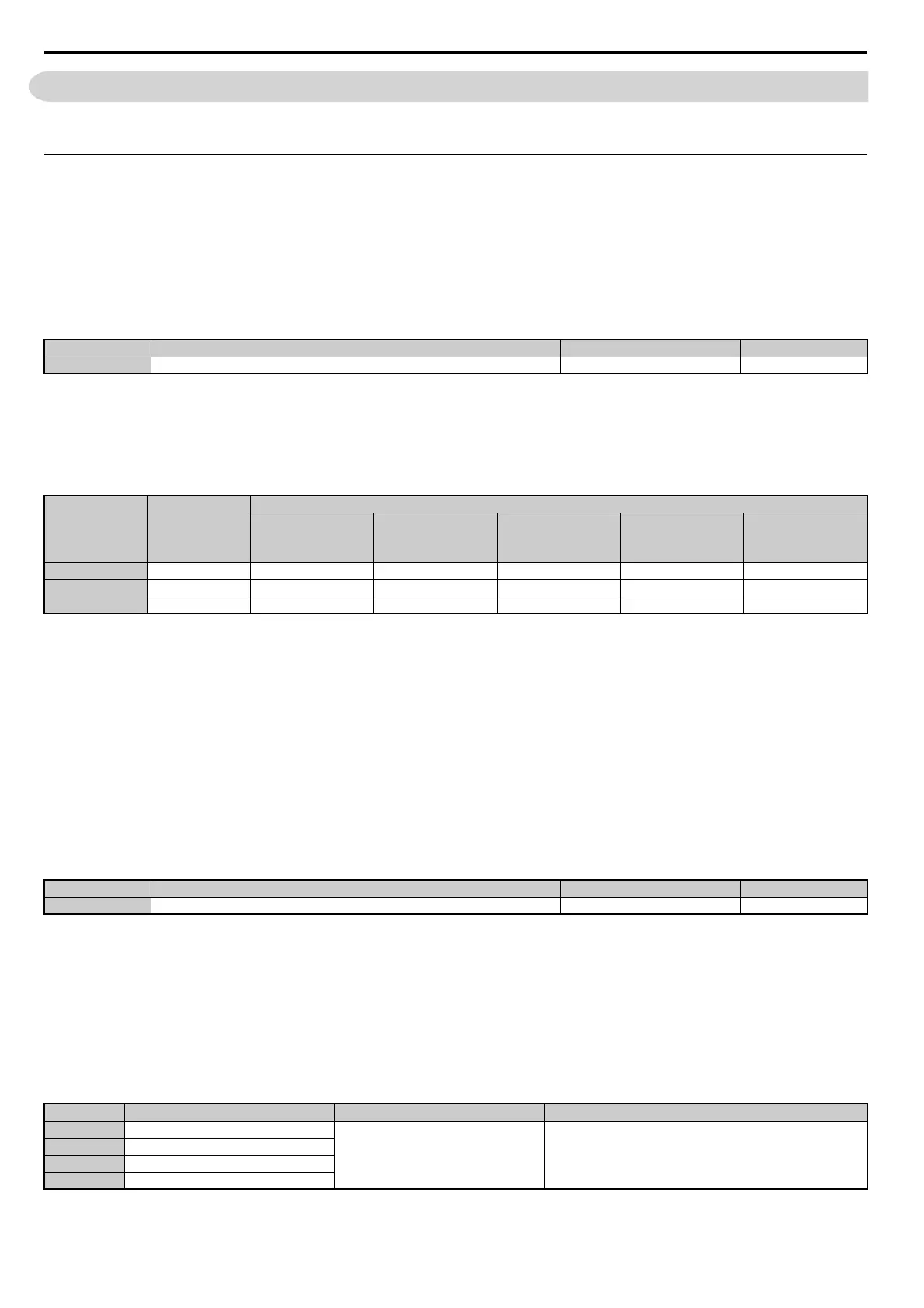
Parameter Name Setting Range Default
E1-01 <1> Input Voltage Setting 155 to 255 V 200 V
Voltage
<1> The braking transistor operation levels are valid for the drive internal braking transistor. If a CDBR braking chopper is used, refer to the
instruction manual (TOBP C720600 00 or TOBP C720600 01) of that unit.
Setting Value of
E1-01
(Approximate Values)
ov Detection Level
Dynamic Braking
Transistor Detection
Level
<1>
(rr Detection Level)
Uv Detection Level
(L2-05)
Desired DC Bus
Voltage during KEB
(L2-11)
ov Suppression /
Stall Prevention Level
(L3-17)
200 V Class All settings 410 V 394 V 190 V 260 V 375 V
400 V Class
setting 400 V 820 V 788 V 380 V 500 V 750 V
setting < 400 V 820 V 788 V 350 V 460 V 750 V
No. Parameter Name Setting Range Default
E1-03 V/f Pattern Selection 0 to F <1>
<1> Parameter setting value is not reset to the default value during drive initialization (A1-03).
F <2>
<2> Settings 0 through E are not available when using any of the vector control modes.
Setting Specification Characteristic Application
0 50 Hz
Constant torque
For general purpose applications. Torque remains constant regardless of
changes to speed.
1 60 Hz
2 60 Hz (with 50 Hz base)
3 72 Hz (with 60 Hz base)