3.5 Terminal Cover
YASKAWA ELECTRIC SIEP C710616 27G YASKAWA AC Drive A1000 Technical Manual 69
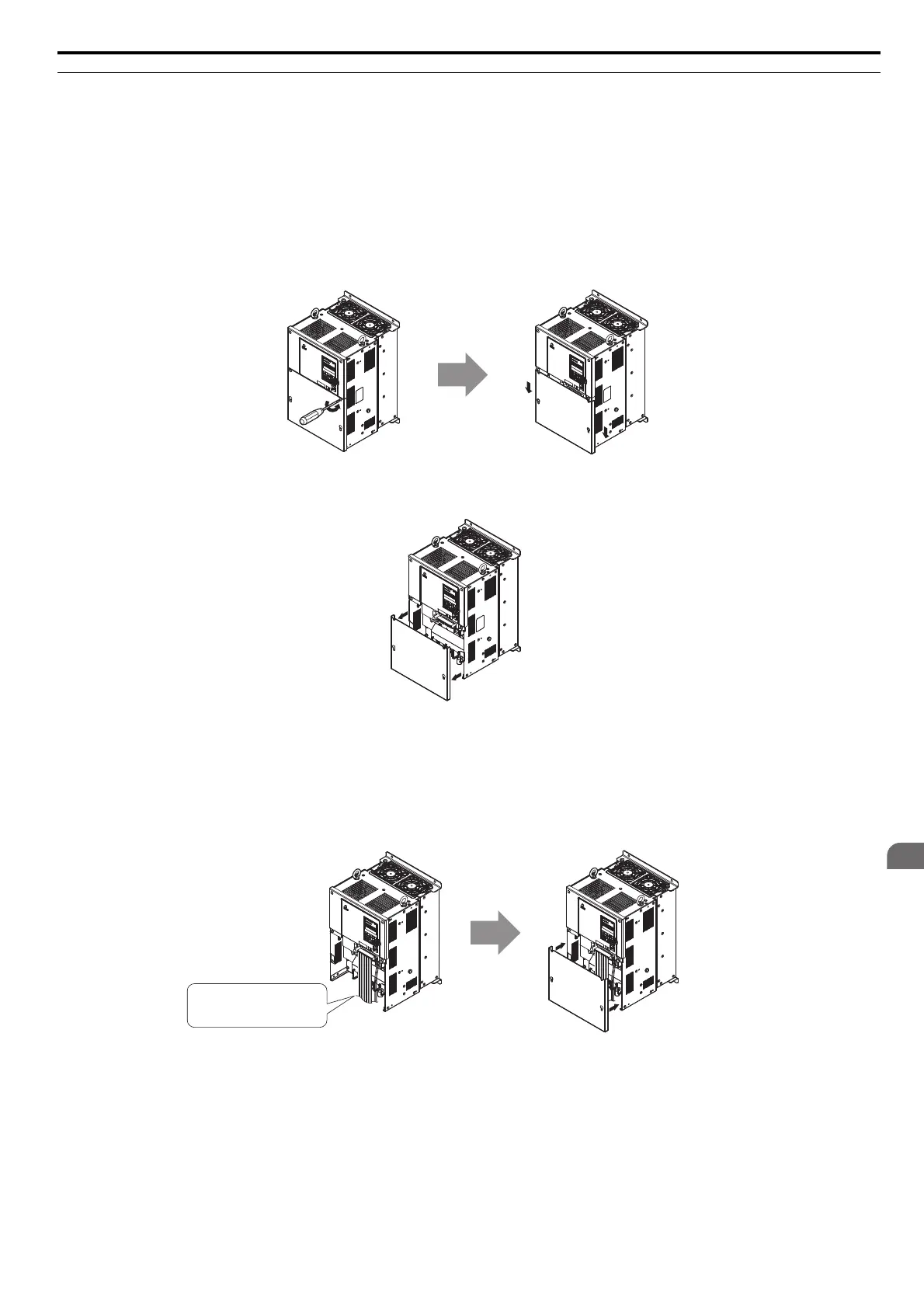
CIMR-A2A0110 to 2A0415, 4A0058 to 4A1200 (IP00 Enclosure)
Removing the Terminal Cover
1. Loosen the screws <1> on the terminal cover, then pull down on the cover.
CAUTION! Crush Hazard. Do not completely remove the cover screws, just loosen them. If the cover screws are removed completely,
the terminal cover may fall off causing an injury. Take special care when removing/reattaching the terminal covers for larger drives.
Figure 3.11
Figure 3.8 Removing the Terminal Cover on an IP00 Enclosure Drive
2. Pull forward on the terminal cover to free it from the drive.
Figure 3.12
Figure 3.9 Removing the Terminal Cover on an IP00 Enclosure Drive
Reattaching the Terminal Cover
Once wiring to the terminal board and other devices is complete, double check all connections and finally reattach the
terminal cover. Refer to Wiring the Main Circuit Terminal on page 82 and Wiring the Control Circuit Terminal on
page 85 for details on wiring.
Figure 3.13
Figure 3.10 Reattaching the Terminal Cover on an IP00 Enclosure Drive
<1> Refer to Terminal Cover on page 68 for details on removing the terminal cover.
The terminal cover or the number of screws for the terminal cover differs in accordance with the drive model. Refer to
Component Names on page 35 for details.
Connect ground wiring first,
followed by the main circuit,
and then wire the control circuit.

 Loading...


