6.6 Operator Programming Errors
YASKAWA ELECTRIC SIEP C710616 27G YASKAWA AC Drive A1000 Technical Manual 357
6.6 Operator Programming Errors
oPE Codes, Causes, and Possible Solutions
An Operator Programming Error (oPE) occurs when a contradictory parameter is set or an individual parameter is set to
an inappropriate value.
The drive will not operate until the parameter or parameters causing
the problem are set correctly. An oPE, however, does
not trigger an alarm or fault output. If an oPE occurs, investigate the cause and refer to oPE Codes, Causes, and Possible
Solutions on page 357 for the appropriate action. When oPE02 or oPE08
appear on the operator display, press the
ENTER button to view U1-18 and see which parameter is causing the oPE.
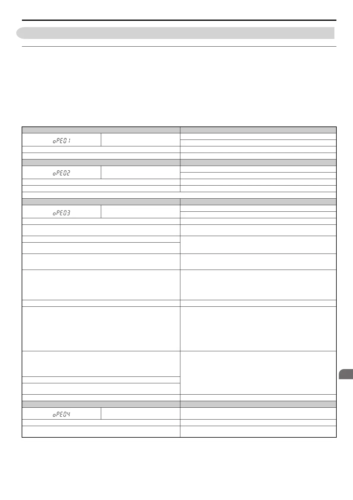
Table 6.17 oPE Codes, Causes, and Possible Solutions
Digital Operator Display Error Name
oPE01
Drive Capacity Setting Fault
Driv
e capacity and the value set to o2-04 do not match.
Cause Possible Solutions
The drive model selection (o2-04) and the actual capacity of the drive are not the same. Correct the value set to o2-04.
Digital Operator Display Error Name
oPE02
Parameter Range Setting Error
Use U1
-18 to find parameters set outside the range.
Cause Possible Solutions
Parameters were set outside the possible setting range. Set parameters to the proper values.
Note: When multiple errors occur at the same time, other errors are given precedence over oPE02.
Digital Operator Display Error Name
oPE03
Multi-Function Input Selection Error
A
contradictory setting is assigned to multi-function contact inputs H1-01 to H1-08.
Cause Possible Solutions
• The same function is assigned
to two multi-function inputs.
• Excludes “Not used” and “External Fault.”
• Ensure all multi-function inputs are assigned to different functions.
• Re-enter the multi-function settings
to ensure this does not occur.
The Up command was set but the Down command was
not, or vice versa (settings 10 vs. 11).
Correctly set functions that need to be enabled in combination with other functions.
The Up 2 command was set but the Down 2 command was not, or vice versa (settings 75 vs.
76).
• Run/Stop command for a 2-wire sequ
ence was set (H1- = 42), but Forward/Reverse
command (H1- = 43) was not.
• “Drive Enable” is set to multi-function input
S1 or S2 (H1-01 = 6A or H1-02 = 6A).
Correctly set functions that need to be enabled in combination with other functions.
• Two of the following functions are
set at the same time:
• Up/Down Command (10 vs. 11)
• Up 2/Down 2 Command (75 vs. 76)
• Hold Accel/Decel Stop (A)
• Analog Frequency Refer
ence Sample/Hold (1E)
• Offset Frequency 1, 2, 3 Calcul
ations (44, 45, 46)
• Check if contradictory settings have been ass
igned to the multi-function input terminals at
the same time.
• Correct setting errors.
The Up/Down command (10, 11) is enabled at the same time as PID cont
rol (b5-01). Disable control PID (b5-01 = 0) or disable the Up/Down command.
Settings for N.C. and N.O. input for the following functions were selected at the same time:
• External Search Command 1 and External Search C
ommand 2 (61 vs. 62)
• Fast Stop N.O. and Fast Stop N.C. (15 vs. 17)
• KEB for Momentary Power Loss and High Slip Braking (65, 66, 7A, 7B vs. 68)
• Motor Switch Command and Accel/
Decel Time 2 (16 vs. 1A)
• KEB Command 1 and KEB Command 2 (65, 66 vs. 7A, 7B)
• FWD Run Command (or REV) and FWD/REV Run Command (2-wire) (40, 41 vs. 42, 43)
• External DB Command and Drive Enable (60 vs. 6A)
• Motor Switch Command and Up 2/Down 2 Command (16 vs. 75, 76)
Check for contradictory settings assigned to the m
ulti-function input terminals at the same
time. Correct setting errors.
One of the following settings was entered while H1- = 2 (External Reference 1/2):
• b1-15 = 4 (Pulse Train Input) but the pulse train input selection is not set for the frequency
reference (
H6-01 > 0)
• b1-15 or b1-16 set to 3 but no option card is connected
• Although b1-15 = 1 (Analog Input) and H3-02 or H3
-10 are set to 0 (Frequency Bias)
Correct the settings for the multi-function input terminal parameters.
H2- = 38
(Drive Enabled) but H1- is not set to 6A (Drive Enable).
H1- = 7E (Direction Detection) although H6-01 is not set to 3 (for V/f Control with PG
using terminal RP as speed feedback input).
H1- = 16 is selected when using PG-RT3.
Correct the setting. PG-RT3 is not available for the application with Motor 2 Selection.
Digital Operator Display Error Name
oPE04
Terminal Board Mismatch Error
Cause Possible Solutions
The drive, control board, or terminal board has been replaced and the parameter settings
be
tween the control board and the terminal board no longer match.
Set A1-03 to 5550 to load the parameter settings stored in the terminal board to the drive.
Initialize parameters after drive replacement by setting A1-03 to 2220 or 3330.