5.4 d: Reference Settings
206 YASKAWA ELECTRIC SIEP C710616 27G YASKAWA AC Drive A1000 Technical Manual
d4-11: Bi-Directional Output Selection
Selects if the frequency reference or PID output value is converted into bi-directional internal frequency reference. Refer
also to the PID block diagram in Figure 5.26 to see how bi-directional output works.
Note: When used in combination with PID control, the bi-directional output function can be enabled or disabled using a digital input
(H1- = 7F)
Setting 0: No Conversion
The frequency reference or PID output value is used as it is without being converted. The drive will operate in the
direction selected from 0 to 100% of the maximum output frequency.
Setting 1: Bi-Directional Output Conversion
When the frequency reference or PID output is below 50%, the drive reverses the selected direction. When it is above
50% the drive works in the selected direction.
d4-12: Stop Position Gain
Sets the gain for adjusting the stopping accuracy when simple positioning is selected as the stopping method (b1-03 = 9).
Increase the value if the motor stops before the desired stop position is reached. Decrease it if the motor stops too late.
Also refer to b1-03: Stopping Method Selection on page 150 for details on simple positioning.
d5: Torque Control
Torque Control is available for CLV and CLV/PM (A1-02 = 3, 7). It allows to define a setpoint for the torque produced
by the motor.
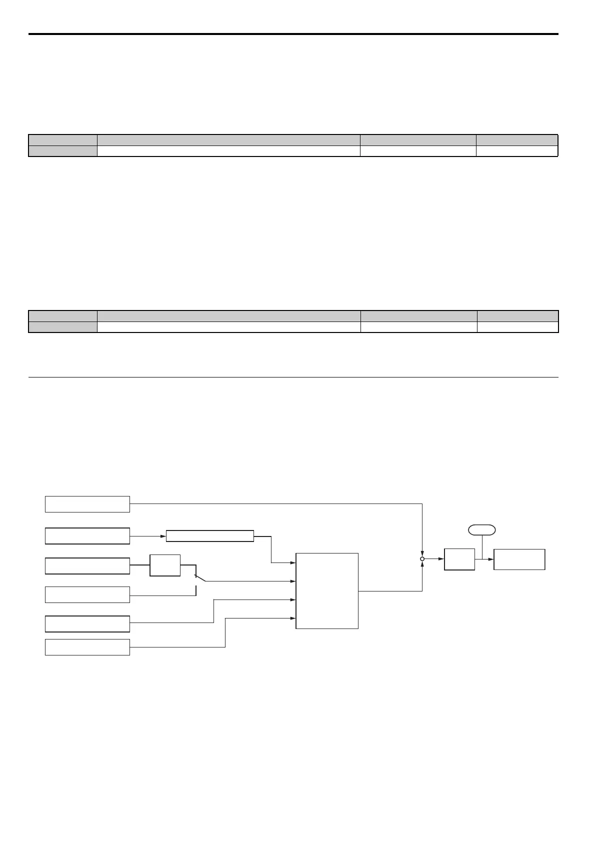
Torque Control Operation
Torque control can be enabled either by setting parameter d5-01 to 1 or by a digital input (H1- = 71). Figure 5.53
illustrates the working principle.
Figure 5.53
Figure 5.53 Torque Control Block Diagram
The externally input torque reference is used as the target value for the motor output torque. If the motor torque reference
and the load torque are not in balance when in Torque Control, the motor accelerates or decelerates. An operation beyond
the speed limit is prevented by compensating the external torque reference value if the motor speed reaches the limit. The
compensation value is calculated using the speed limit, speed feedback, and the speed limit bias.
If an external torque compensation value is input, it is added to
the speed limit compensated torque reference value. The
value calculated is limited by the L7- settings, and is then used as the internal torque reference,
which can be
monitored in U1-09. The L7- settings have highest priority, i.e., the motor cannot be
operated with a higher torque
than the L7- settings, even if the external torque reference
value is increased.
No. Parameter Name Setting Range Default
d4-11 Bi-Directional Output Selection 0 or 1 0
No. Parameter Name Setting Range Default
d4-12 Stop Position Gain 0.50 to 2.55 1.00
Torque Compensation
External Torque Reference
External Speed Limit
Speed Limit set in d5-04
Speed Feedback
Speed Limit Bias d5-05
Soft
Starter
d5-03
1
2
C1- , C2-
Torque Reference Delay
d5-02
Torque
Limits
L7-
Internal Torque
Reference
+
Compensated torque
reference
d5-08
+
U1-09
Speed Limiter