A.6 Drive Derating Data
YASKAWA ELECTRIC SIEP C710616 27G YASKAWA AC Drive A1000 Technical Manual 447
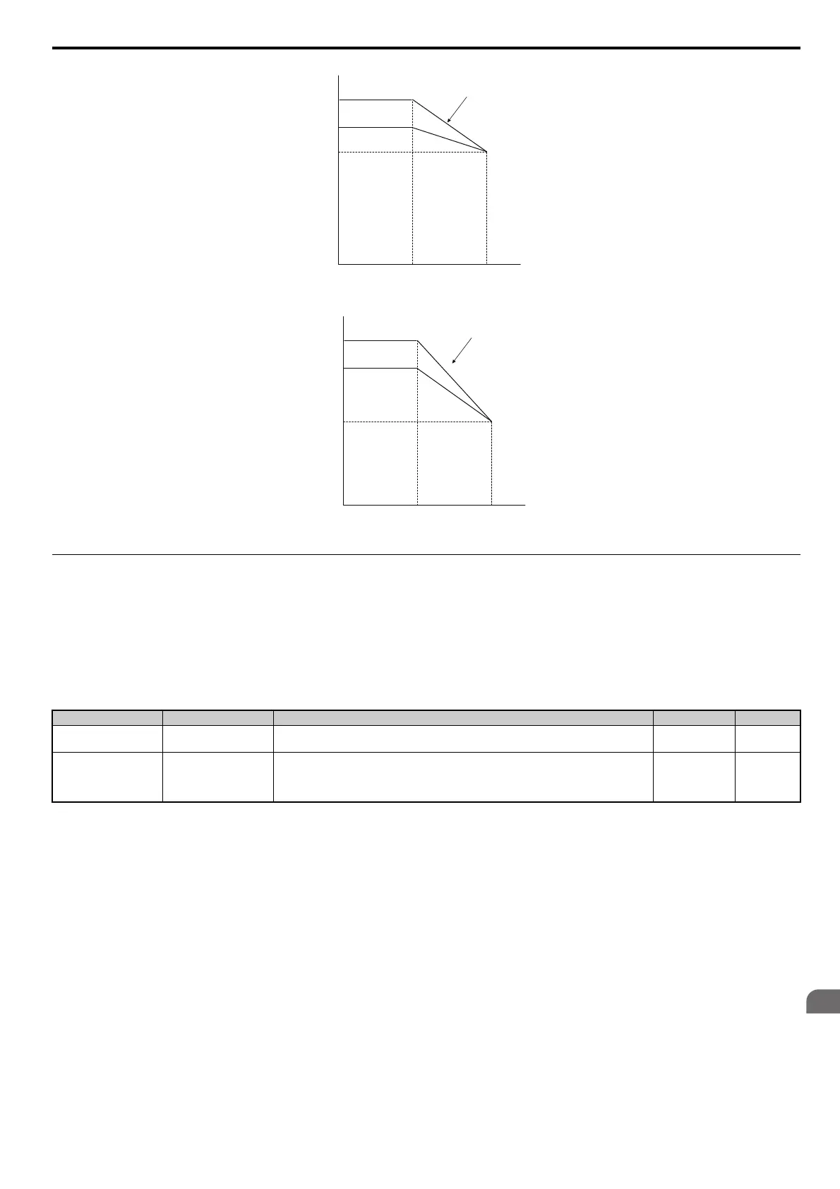
Figure A.5
Figure A.5 Carrier Frequency Derating (CIMR-A4A0515 and 4A0675)
Figure A.6
Figure A.6 Carrier Frequency Derating (CIMR-A4A0930 and 4A1200)
Temperature Derating
To ensure the maximum performance life, the drives output current must be derated like shown in Figure A.7 when the
drive is installed in areas with high ambie
nt temperature or if drives are Side-by-Side mounted in a cabinet. In order to
ensure reliable drive overload protection, the parameters L8-12 and L8-35 must also be set according to the installation
conditions.
Parameter Settings
0: IP00 Enclosure
Drive operation between -10C and 50C allows 100% continuous current without derating.
1: Side-by-Side Mounting
Drive operation between -10C and 30C allows 100% continuous current without derating. Operation between 30C
and 50C
requires output current derating.
2: IP20/NEMA 1, UL Type 1 Enclosure
Drive operation between -10C and 40C allows 100% continuous current without derating. Operation between 40C
and 50C
requires output current derating.
No. Name Description Range Def.
L8-12
Ambient Temperature
Setting
Adjust the drive overload (oL2) protection level when the drive is installed in an environment
that exceeds its ambient temperature rating.
-10 to 50 40°C
L8-35
Installation Method
Selection
0: IP00 Enclosure
1: Side-by-Side Mounting
2: IP20/NEMA 1, UL Type 1 Enclosure
3: Finless Drive or External Heatsink Installation
0 to 3 0
5 kHz
2 kHz
0
4A0515, 4A0675
Normal Duty
Heavy Duty
83% of HD
5 kHz
2 kHz
Normal Duty
Heavy Duty
62.5% of HD
0
4A0930,4A1200