198 YASKAWA ELECTRIC SIEP C710616 27G YASKAWA AC Drive A1000 Technical Manual
5.4 d: Reference Settings
5.4 d: Reference Settings
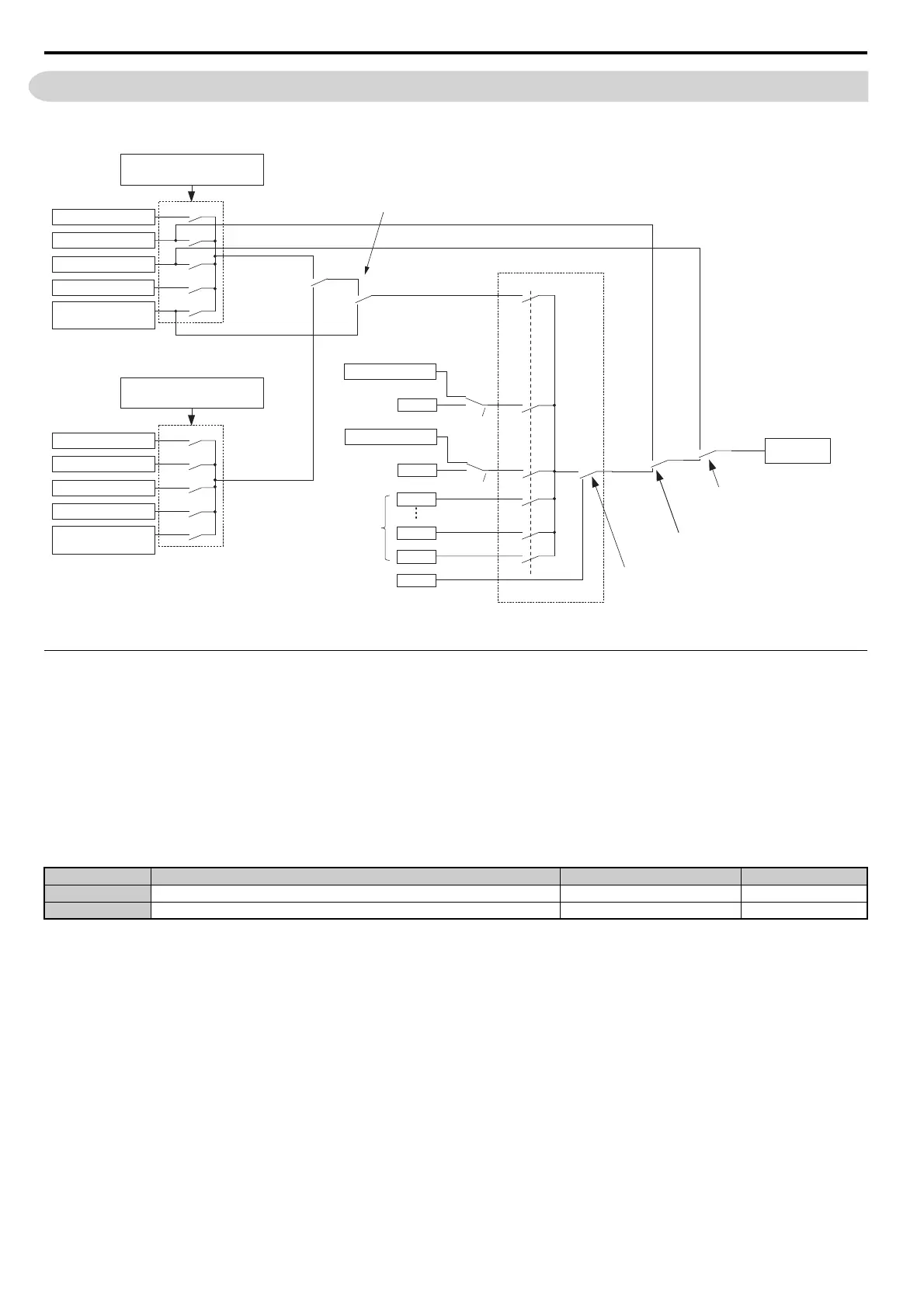
The figure below gives an overview of the reference input, selections, and priorities.
Figure 5.44
Figure 5.44 Frequency Reference Setting Hierarchy
d1: Frequency Reference
d1-01 to d1-17: Frequency Reference 1 to 16 and Jog Frequency Reference
Up to 17 preset frequency references (including the Jog reference) can be programmed in the drive. The drive lets the
user switch between these frequency references during run by using the digital input terminals. The drive uses the
acceleration and deceleration times that have been selected when switching between each frequency reference.
The Jog frequency must be selected by a separa
te digital input and overrides all other frequency references.
The multi-speed references 1, 2, and 3 ca
n be provided by analog inputs.
Multi-Step Speed Selection
To use several speed references for a multi-step speed sequence, set the H1- parameters to 3, 4, 5, and 32. To assign
the Jog reference to a digital input, set H1- to 6.
Notes on using analog inputs as Multi-Step Speed 1, 2, and 3:
• Multi-S
tep Speed 1
When setting terminal A1’s analog input
to Multi-Step Speed 1, set b1-01 to 1, and when setting d1-01 (Frequency
Reference 1) to Multi-Step Speed 1, set b1-01 to 0.
No.
<1> The upper limit is determined by the maximum output frequency (E1-04) and upper limit for the frequency reference (d2-01).
<2> Setting units are determined by parameter o1-03. The default is “Hz” (o1-03 = 0) in V/f, V/f w/PG, OLV, CLV, and OLV/PM control modes.
The default for AOLV/PM and CLV/PM control modes expresses the frequency reference as a percentage (o1-03 = 1).
Parameter Name Setting Range Default
d1-01 to d1-16 Frequency Reference 1 to 16 0.00 to 400.00 Hz <1> <2> 0.00 Hz <2>
d1-17 Jog Frequency Reference 0.00 to 400.00 Hz <1> <2> 6.00 Hz <2>
MS 2
Terminal A2
Digital Input
H1- = 2
Terminal A3
d1-03
H3-06 = 3
H3-06 = 3
Terminal A1/A2/A3
Frequency
Reference
Remote
Set to supply the
auxiliary frequency reference
Local
MEMOBUS comm.
d1-01
(Freq.Ref 1)
b1-01
(Freq. Reference Source 1)
Pulse Train Input
=3
=2
=1
=0
=4
Option Card
MEMOBUS comm.
d1-01
(Freq. Ref. 1)
Pulse Train Input
=3
=2
=1
=0
=4
Option card
Frequency
Reference
4 through 16
Jog Frequency
Multi-Step Speed
NetRef ComRef
d1-04
d1-15
d1-16
d1-17
Terminal A1/A2/A3
d1-02
0
1
Memobus Register 0001h, bit 4 if
standard 2 wire sequence selected,
usually 0
Set from Communications
Option Card, usually 0
0
1
0
1
b1-15
(Freq. Reference Source 2)
H3-10 = 2
H3-10 = 2
MS 1
MS 3
MS 4
MS 15
MS 16
Jog
Open
Close
LO/RE Key on Digital Operator or
Digital Input H1- = 1
Digital Input (H1-)
Jog Reference (=6),
FJOG(=12), RJOG(=13)