3.9 Control Circuit Wiring
84 YASKAWA ELECTRIC SIEP C710616 27G YASKAWA AC Drive A1000 Technical Manual
Output Terminals
Table 3.8 lists the output terminals on the drive. Text in parenthesis indicates the default setting for each multi-function
output.
Table 3.8 Control Circuit Output Terminals
Serial Communication Terminals
Table 3.9 Control Circuit Terminals: Serial Communications
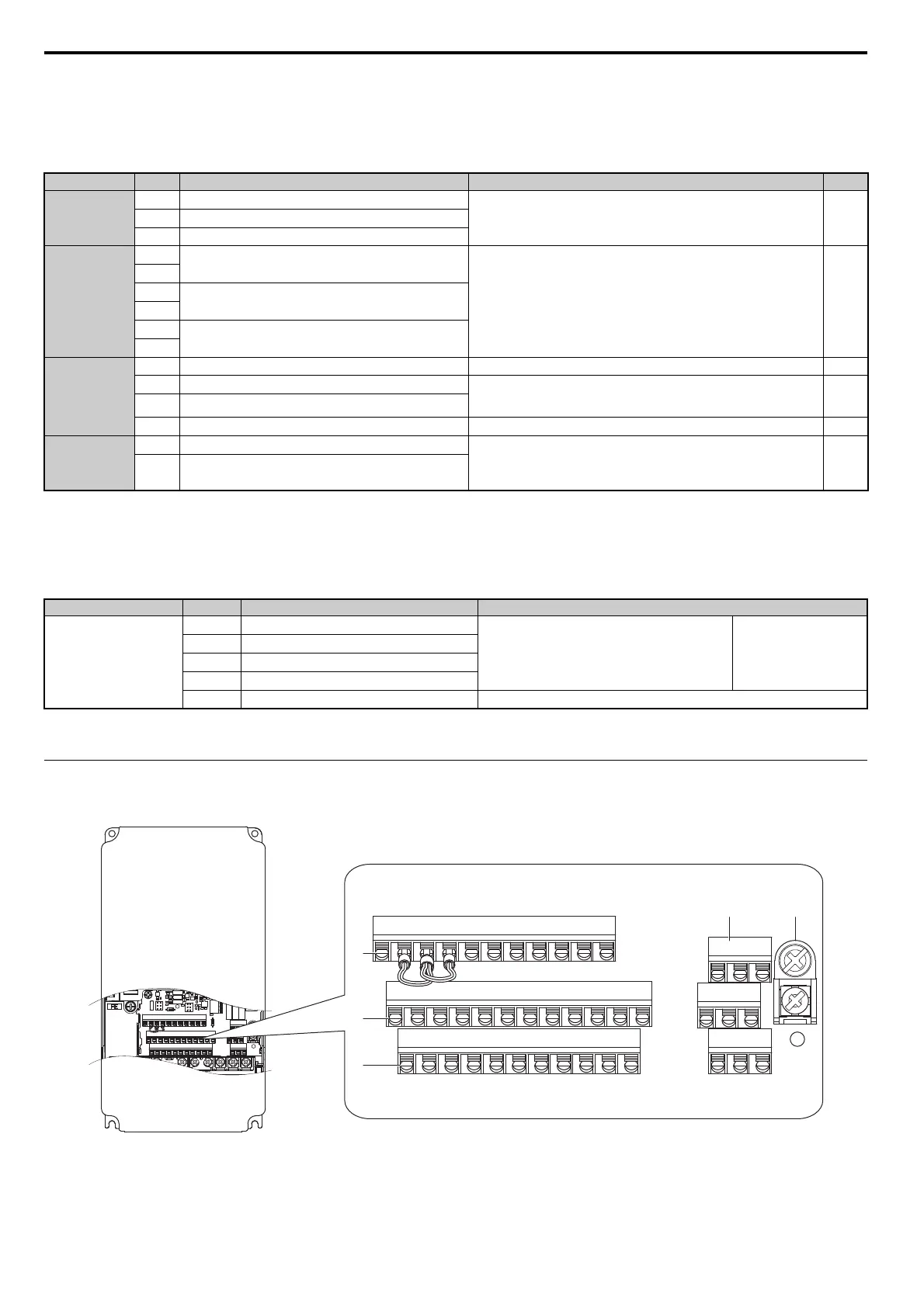
Terminal Configuration
Control circuit terminals should are arranged as shown in Figure 3.22.
Figure 3.25
Figure 3.22 Control Circuit Terminal Arrangement
Type
<1> Refrain from assigning functions to digital outputs that involve frequent switching, as doing so may shorten relay performance life. Switching
life is estimated at 200,000 times (assumes 1 A, resistive load).
No. Terminal Name (Function) Function (Signal Level) Default Setting Page
Fault Relay Output
MA
N.O. output (Fault)
30 Vdc, 10 mA to 1 A; 250 Vac, 10 mA to 1 A
Minimum load: 5 Vdc, 10 mA
246
MB
N.C. output (Fault)
MC
Fault output common
Multi-Function
Digital Output
<1>
M1
Multi-function digital output (During run)
30
Vdc, 10 mA to 1 A; 250 Vac, 10 mA to 1 A
Minimum load: 5 Vdc, 10 mA
246
M2
M3
Multi-function digital output (Zero Speed)
M4
M5
Multi-function digital output (Speed Agree 1)
M6
Monitor Output
MP
Pulse train output (Output frequency) 32 kHz (max) 264
FM
Analog monitor output 1 (Output frequency)
-10 t
o +10 Vdc, 0 to +10 Vdc, or 4-20 mA
Use jumper S5 on the terminal board to select between voltage or current output
signals.
262
AM
Analog monitor output 2 (Output current)
AC
Monitor common 0 V
–
Safety Monitor
Output
DM+
Safety monitor output
Out
puts status of Safe Disable function. Closed when both Safe Disable
channels are closed. Up to +48 Vdc 50 mA Slide the switch S6 to select N.C. or
N.O. as the state of the DM+ and DM- terminals for EDM output as explained
on 91 page.
600
DM-
Safety monitor output
Type
<1> Enable the termination resistor in the last drive in a MEMOBUS/Modbus network by setting DIP switch S2 to the ON position. For more
information on the termination resistor, see Control I/O Connections on page 88.
No. Signal Name Function (Signal Level)
MEMOBUS/Modbus
Communication
<1>
R+
Communications input (+)
M
EMOBUS/Modbus communication: Use a RS-485 or
RS-422 cable to connect the drive.
RS-422/RS-485
MEMOBUS/Modbus
communication protocol
115.2 kbps (max.)
R-
Communications input (-)
S+
Communications output (+)
S-
Communications output (-)
IG
Shield ground 0 V
A – Terminal Block (TB 2) D – Terminal Block (TB 3)
B – Terminal Block (TB 5) E – Terminal Block (TB 4)
C – Terminal Block (TB 1)
E(G)
HC H1 H2 DM+ DM- IG R+ R- S+ S-
S1 S2 S3 S4 S5 S6 S7 S8 SN SC SP
V+ AC V- A1 A2 A3 FM AM AC MP RP AC
A B
E
D
C
MA MB MC
M1 M2 M5
M3 M6 M4
E(G)
HC H1 H2 DM+ DM- IG R+ R- S+ S-
S1 S2 S3 S4 S5 S6 S7 S8 SN SC SP
V+ AC V- A1 A2 A3 FM AM AC MP RP AC