5.9 n: Special Adjustments
YASKAWA ELECTRIC SIEP C710616 27G YASKAWA AC Drive A1000 Technical Manual 303
n2: Speed Feedback Detection Control (AFR) Tuning
These parameters are used to achieve speed stability when a load is suddenly applied or removed.
Note: Before making changes to the AFR parameters, make sure all motor parameters are set properly or perform Auto-Tuning.
n2-01: Speed Feedback Detection Control (AFR) Gain
Sets the internal speed feedback detection control gain in the AFR.
Normally there is no need to adjust n2-01 from the default setting. Make adjustments in the following cases:
• If hunting occurs, increase the setting value in steps of 0.05 while checking the response.
• If response is low, decrease the setting value
in steps of 0.05 while checking the response.
n2-02, n2-03: Speed Feedback Detection Control (AFR) Time Constant 1, 2
Parameter n2-02 sets the time constant normally used by AFR.
Parameter n2-03 sets the time constant during
Speed Search or regenerative operation.
Note: Parameter n2-02 cannot be set higher than n2-03 or an oPE08 error will result.
These parameters rarely need to be changed. Adjust settings only under the following conditions:
• If hunting occurs, increase n2-02. If response is low
, decrease it.
• Increase n2-03 if overvoltage occurs with high inertia loads at the
end of acceleration or with sudden load changes.
• If setting n2-02 to a higher value, also increase
C4-02 (Torque Compensation Delay Time Constant 1) proportionally.
• If setting n2-03 to a higher value, also increase
C4-06 (Torque Compensation Delay Time Constant 2) proportionally.
n3: High Slip Braking (HSB) and Overexcitation Braking
High Slip Braking (V/f)
HSB works in V/f Control only and is used to decrease the stopping time compared to normal deceleration without using
dynamic braking options. HSB stops the motor by reducing the output frequency in large steps, thus producing a high
slip. Regenerative energy created from decelerating the load is dissipated in the motor windings through increased motor
slip. Because of the increased temperature of the motor windings, HSB should not be used for frequently stopping the
motor. The duty cycle should be around 5% or less.
Notes on using High Slip Braking:
• The deceleration time that has been set is ignored during HSB. Use Overexcitation Deceleration 1 (L3-04 = 4) or a
dynamic braking option if the motor has to be stopped in a defined time.
• Braking time varies based on the load
inertia and motor characteristics.
• HSB and KEB Ride-Thru cannot be used simultaneously
. If enabled at the same time, an oPE03 will occur.
• HSB must be triggered by a digital input
set to H1- = 68. Once the HSB command is given, it is not possible to
restart the drive until the motor has stopped completely and the Run command is cycled.
• Use parameters n3-01 throug
h n3-04 for adjusting HSB.
n3-01: High Slip Braking Deceleration Frequency Width
Sets the step width for frequency reduction during HSB. Increase n3-01 if DC bus overvoltage (ov) occurs during HSB.
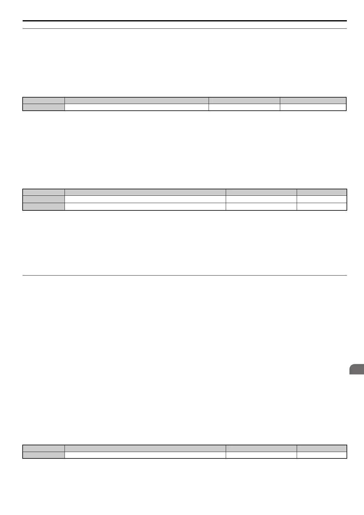
No. Name Setting Range Default
n2-01 Speed Feedback Detection Control (AFR) Gain 0.00 to 10.00 1.00
No. Name Setting Range Default
n2-02
Speed Feedback Detection Control (AFR) Time Constant 1
0 to 2000 ms 50 ms
n2-03
Speed Feedback Detection Control (AFR) Time Constant 2
0 to 2000 ms 750 ms
No. Name Setting Range Default
n3-01 High Slip Braking Deceleration Frequency Width 1 to 20% 5%