8.5 Installing Peripheral Devices
432 YASKAWA ELECTRIC SIEP C710616 27G YASKAWA AC Drive A1000 Technical Manual
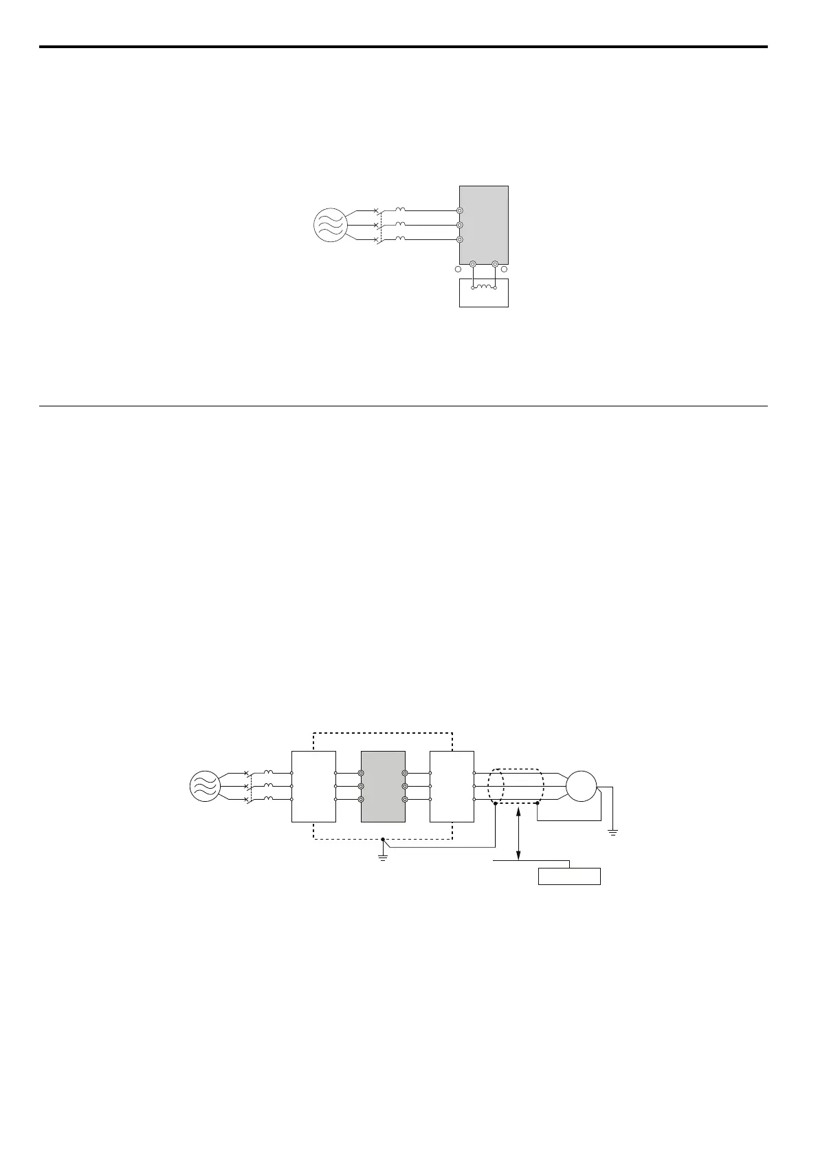
Connecting a DC Reactor
A DC reactor can be installed to drive models CIMR-A2A0004 to 0081 and 4A0002 to 0044. When installing a DC
reactor, ensure the jumper between terminals +1 and +2 (terminals are jumpered for shipment) is removed. The jumper
must be installed if no DC reactor is used. Refer to Figure 8.25 for an example of DC reactor wiring.
Figure 8.23
Figure 8.25 Connecting a DC Reactor
Connecting a Noise Filter
Reducing Radiated, Conducted, and Induced Noise
Drives generate noise that can potentially affect surrounding devices like PLCs, etc.
• Radiate
d Noise: Electromagnetic waves noise throughout the radio bandwidth radiated from the drive and cables.
• Conduc
ted Noise: Noise generated by the drive and emitted to through the power lines.
• Induced Noise: Noise gen
erated by electromagnetic induction can affect control signal lines.
Take the following measurements to
prevent noise causing malfunction of other drives or devices:
• Install all components on a well grounded metal plate.
• Keep the motor cable as short as possible.
• Use noise filters on the input side of
the drive to reduce conducted noise.
• Install noise filters on the input and output side of the
drive, install the drive in a metal enclosure panel and use a
shielded motor cable to reduce radiated noise.
• Use shielded motor and control circuit lines a
nd lay control circuit lines at least 30 cm away from power lines in order
to prevent malfunction due to induced noise.
Figure 8.24
Figure 8.26 Reducing Radio Frequency Noise
A–Power supply C–Drive
B – MCCB D – DC reactor
A – Metal enclosure F – Shielded motor cable
B – Power supply G – Motor
C – Input noise filter H – Separate at least 30 cm
D – Drive I – Control signal lines
E – Output noise filter J – Controller
A
C
D
R/L1
B
S/L2
T/L3
1+2+
J
I
H
C
E
D
B
F
A
R/L1
MCCB
S/L2
T/L3
U/T1
V/T2
W/T3
M
G

 Loading...


