C.9 MEMOBUS/Modbus Data Table
560 YASKAWA ELECTRIC SIEP C710616 27G YASKAWA AC Drive A1000 Technical Manual
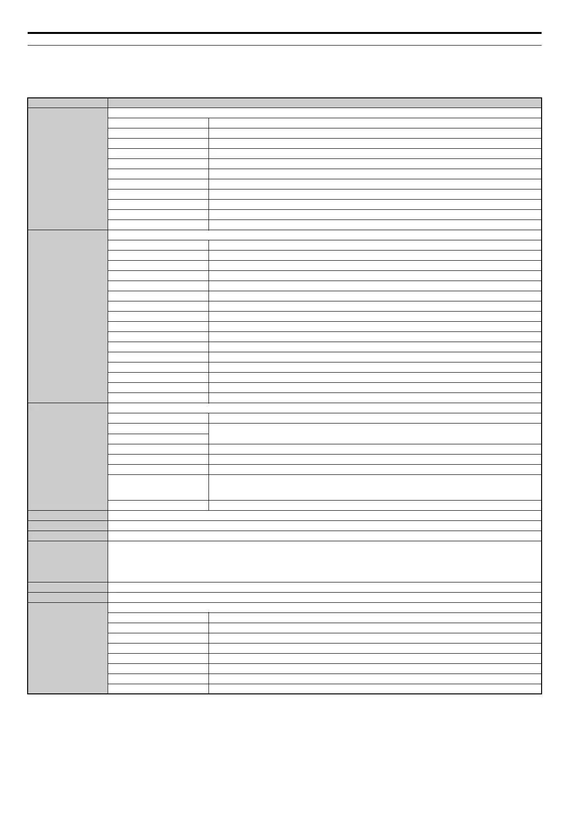
Monitor Data
Monitor data can be read only.
Register No. Contents
0020H
Drive Status 1
bit 0 During Run
bit 1 During Reverse
bit 2 Drive Ready
bit 3 Fault
bit 4 Data Setting Error
bit 5 Multi-Function Contact Output 1 (terminal M1-M2)
bit 6 Multi-Function Contact Output 2 (terminal M3-M4)
bit 7 Multi-Function Contact Output 3 (terminal M5-M6)
bit 8 to bit D Reserved
bit E When ComRef has been enabled
bit F When ComCtrl has been enabled
0021H
Fault Contents 1
bit 0 Overcurrent (oC), Ground fault (GF)
bit 1 Drive Overheat Warning (ov)
bit 2 Drive Overload (oL2)
bit 3 Overheat 1 (oH1), Drive Overheat Warning (oH2)
bit 4 Dynamic Braking Transistor Fault (rr), Braking Resistor Overheat (rH)
bit 5 Reserved
bit 6 PID Feedback Loss (FbL / FbH)
bit 7 External Fault (EF0 to EF8)
bit 8 CPF: Hardware Fault (includes oFx)
bit 9 Motor Overload (oL1), Overtorque Detection 1/2 (oL3/oL4), Undertorque Detection 1/2 (UL3/UL4)
bit A PG Disconnected (PGo), PG Hardware Fault (PGoH), Overspeed (oS), Speed Deviation (dEv),
bit B Main Circuit Undervoltage (Uv)
bit C DC Bus Undervoltage (Uv1), Control Power Supply Voltage Fault (Uv2), Undervoltage 3 (Uv3)
bit D Output Phase Loss (LF), Input Phase Loss (PF)
bit E MEMOBUS/Modbus Communication Error (CE), Option Communication Error (bUS)
bit F External Digital Operator Connection Fault (oPr)
0022H
Data Link Status
bit 0 Writing data or switching motors
bit 1
Reserved
bit 2
bit 3 Upper or lower limit error
bit 4 Data conformity error
bit 5 Writing to EEPROM
bit 6
0: Write into EEPROM.
1: Write in RAM only.
Note: Enabled only when H5-17=1.
bit 7 to bit F Reserved
0023H Frequency Reference, <1>
0024H Output Frequency, <1>
0025H Output Voltage Reference, 0.1 V units (units are determined by parameter H5-10)
0026H
Output Current
Note: Display is in the following units:
CIMR-A2A0004 to 2A0040 and CIMR-A4A0002 to 4A0023: 0.01 A
CIMR-A2A0056 to 2A0415 and CIMR-A4A0031 to 4A0675: 0.1 A
CIMR-A4A0930 and 4A1200: 1 A
0027H Output Power
0028H Torque Reference
0029H
Fault Contents 2
bit 0 Output Short-Circuit or IGBT Fault (SC)
bit 1 Ground Fault (GF)
bit 2 Input Phase Loss (PF)
bit 3 Output Phase Loss (LF)
bit 4 Braking Resistor Overheat (rH)
bit 5 Reserved
bit 6 Motor Overheat Fault (PTC Input) (oH4)
bit 7 to bit F Reserved