C.3 Connecting to a Network
YASKAWA ELECTRIC SIEP C710616 27G YASKAWA AC Drive A1000 Technical Manual 549
MEMOBUS/Modbus
Communications
C
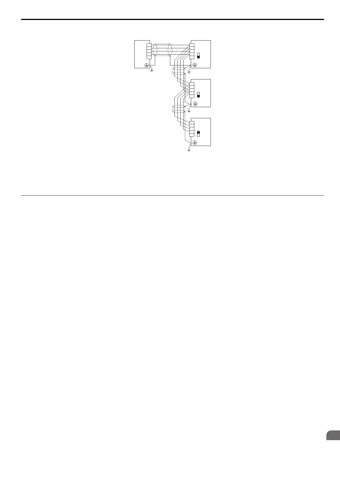
RS-422 Interface
Figure C.4
Figure C.4 RS-422 Interface
Note: 1. Turn on the DIP switch S2 on the drive that is located at the end of
the network. All other slave devices must have this DIP switch set
to the OFF position.
2. Set H5-07 to 0 when using RS-422 inter
face in a point-to-point circuit.
Set H5-07 to 1 when using RS-422 interface in a multi-drop circuit.
Network Termination
The two ends of the MEMOBUS/Modbus network line have to be terminated. The drive has a built in termination
resistor that can be enabled or disabled using DIP switch S2. If a drive is located at the end of a network line, enable the
termination resistor by setting DIP switch S2 to the ON position. Disable the termination resistor on all slaves that are not
located at the network line end.
Refer to MEMOBUS/Modbus Termination on page 91 for details on setting S2.
R–
R+
S
–
S+
IG
PLC
Drive
Drive
Drive
S–
S+
R
–
R+
IG
S
–
S+
R
–
R+
IG
S
–
S+
R
–
R+
IG
S2
OFF
S2
OFF
S2
ON