6.2 Motor Performance Fine-Tuning
328 YASKAWA ELECTRIC SIEP C710616 27G YASKAWA AC Drive A1000 Technical Manual
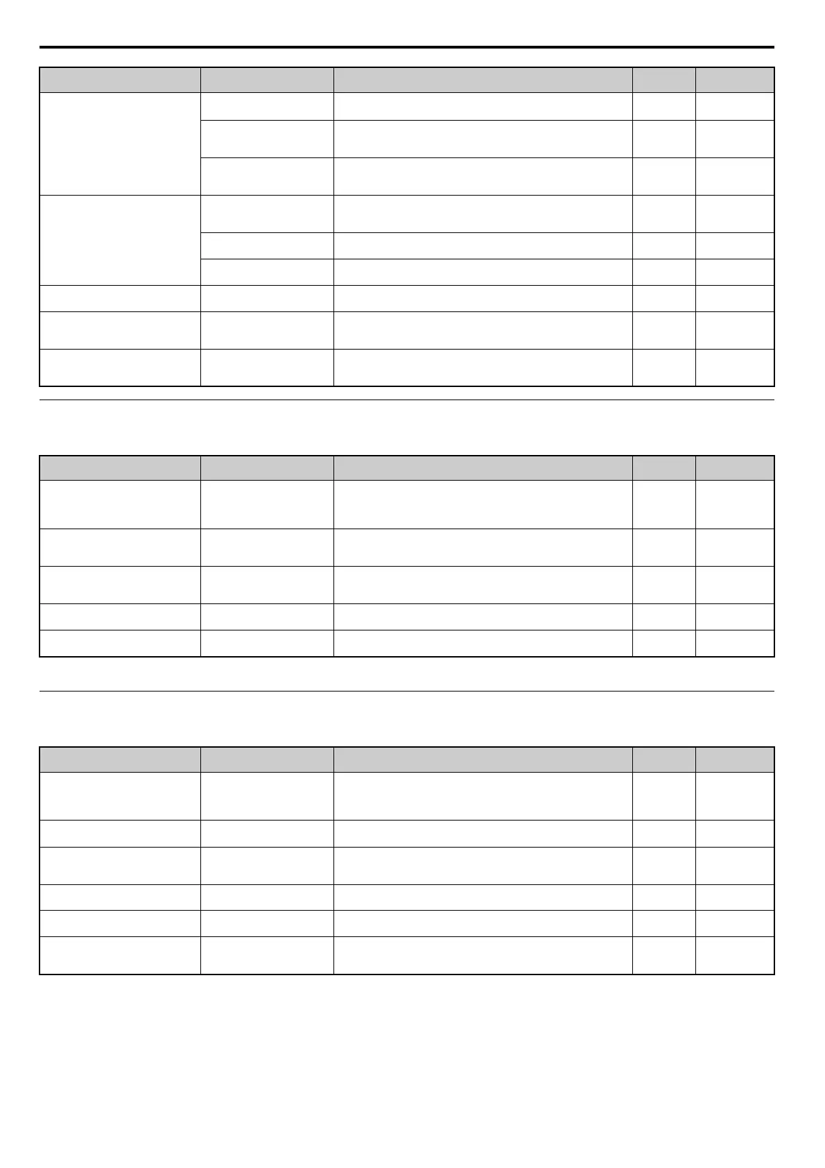
Fine-Tuning Advanced Open Loop Vector Control for PM Motors
Table 6.5 Parameters for Fine-Tuning Performance in AOLV/PM
Fine-Tuning Closed Loop Vector Control for PM Motors
Table 6.6 Parameters for Fine-Tuning Performance in CLV/PM
Oscillation at start or the motor stalls
Pull-In Current during Accel/
De
cel (for PM Motors) (n8-51)
Increase the pull-in current set in n8-51 50%
Increase in steps
of 5%
DC Injection Braking Current
(b2-02
), DC Injection Time at
Start (b2-03)
Use DC Injection Braking at start to align the rotor. Be aware that this
oper
ation can cause a short reverse rotation at start.
b2-02 = 50%
b2-03 = 0.0 s
b2-03 = 0.5 s
Increase b2-02 if
ne
eded
Load Inertia Ratio (n8-55)
Increase the load inertia ratio.
No
te: Setting this value too high can cause overcompensation and motor
oscillation.
0
Close to the actual
loa
d inertia ratio
Stalling or oscillation occur when load
is
applied during constant speed
Pull-In Current Compensation
T
ime Constant (for PM Motors)
(n8-47)
Decrease n8-47 if hunting occurs
during constant speed 5.0 s
Reduce in
increments of 0.2 s
Pull-In Current (for PM Motors)
(n8-48)
Increase the pull-in current in n8-48. 30%
Increase in
i
ncrements of 5%
Load Inertia Ratio (n8-55) Increase the load inertia ratio. 0
Close to the actual
loa
d inertia ratio
Hunting or oscillation occur
Speed feedback De
tection Gain
(for PM Motors) (n8-45)
Increase the speed feedback detectio
n gain in n8-45. 0.8
Increase in
i
ncrements 0.05
STO fault trips even if the load is not
to
o high
Induced Voltage Constant (for
PM Motors) (E5-09 or E5-24)
• Check and adjust the induced
voltage constant.
• Check the motor name plate, the dat
a sheet or contact the motor
manufacturer for getting data.
dep. on drive
capacity
and
motor code
Refer to the motor
data sheet or the
nameplate.
Stalling or STO occurs at high speed as
th
e output voltage becomes saturated.
Output Voltage Limit (for PM
Motors) (n8-62)
Set the value of the input voltage to parameter n8-62.
Never set the value higher than the actual input voltage.
200 Vac or 400
Va c
Set the value lower
th
an the actual
input voltage.
Problem Parameter No. Corrective Action Default
Suggested
Setting
• Poor torque or speed response
• Motor hunting and oscillation
ASR Proportional Gain 1
(C5-01)
ASR Proportional Gain 2
(C5-03)
• If motor torque and speed response are
too slow, gradually increase the
setting by 5.
• If motor hunting and oscillation occur, decrease the setting.
• Parameter C5-03 needs to be adjusted only if C5-05 > 0.
10.00 5.00 to 30.00
<1>
<1> Optimal settings will differ between no-load and loaded operation.
• Poor torque or speed response
• Motor hunting and oscillation
ASR Integral Time 1 (C5-02)
ASR Integral Time 2 (C5-04)
• If motor torque and speed response are
too slow, decrease the setting.
• If motor hunting and oscillation occur, increase the setting.
• Parameter C5-03 needs to be adjusted only if C5-05 > 0
0.500 s
0.300 to
1.000 s
<1>
Trouble maintaining the ASR
proportional gain or the integral time at
the low or high end of the speed range
ASR Gain Switching Frequency
(C
5-07)
Have the drive switch between two different ASR proportional gain and
integral time settings based on the output frequency.
0.0%
0.0 to Max min
-1
Motor hunting and oscillation
ASR Primary Delay Time
C
onstant (C5-06)
If the load is less rigid and subject to oscillation, increase this setting. 0.010 s
0.016 to
0.035 s
<1>
Motor stalling makes normal operation
impossible
Motor parameters
(E1-, E5-)
Check the motor parameter settings. – –
Problem Parameter No. Corrective Action Default
Suggested
Setting
• Poor torque or speed response
• Motor hunting and oscillation
ASR Proportional Gain 1
(C5-01)
ASR Proportional Gain 2
(C5-03)
• If motor torque and speed response are
too slow, gradually increase the
setting by 5.
• If motor hunting and oscillation occur, decrease the setting.
• Perform ASR Gain Auto-Tuning if possible
20.00 10.00 to 50.00
<1>
<1> Optimal settings will differ between no-load and loaded operation.
• Poor torque or speed response
• Motor hunting and oscillation
ASR Integral Time 1 (C5-02)
ASR Integral Time 2 (C5-04)
• If motor torque and speed response are too slow, decrease the setting.
• If motor hunting and oscillation occur, increase the setting.
0.500 s
0.300 to
1.000 s
<1>
ASR proportional gain or the integral
time at the low or high end of the speed
range
ASR Gain Switching Frequency
(C
5-07)
Have the drive switch between two different ASR proportional gain and
integral time settings based on the output frequency.
0.0%
0.0 to Max min
-1
Motor hunting and oscillation
ASR Primary Delay Time
Constant (C5-06)
If the load is less rigid and subject to oscillation, increase this setting. 0.016 s
0.004 to
0.020 s
<1>
Motor stall makes normal operation
impossible
Motor parameters
(E1-, E5-)
Check the motor parameter settings. – –
Overshoot or undershoot at speed
changes wi
th high inertia load.
Feed Forward Control (n5-01)
Inertia Auto-Tuning (T2-01 = 8)
Enable Feed Forward Control by setting parameter n5-01 = 1 and perform
Inertia Auto-Tuning. If Auto-Tuning cannot be performed set parameters
C5-17, C5-18 and n5-03 manually.
0 1
Problem Parameter No. Corrective Action Default
Suggested
Setting