1.5 Component Names
42 YASKAWA ELECTRIC SIEP C710616 27G YASKAWA AC Drive A1000 Technical Manual
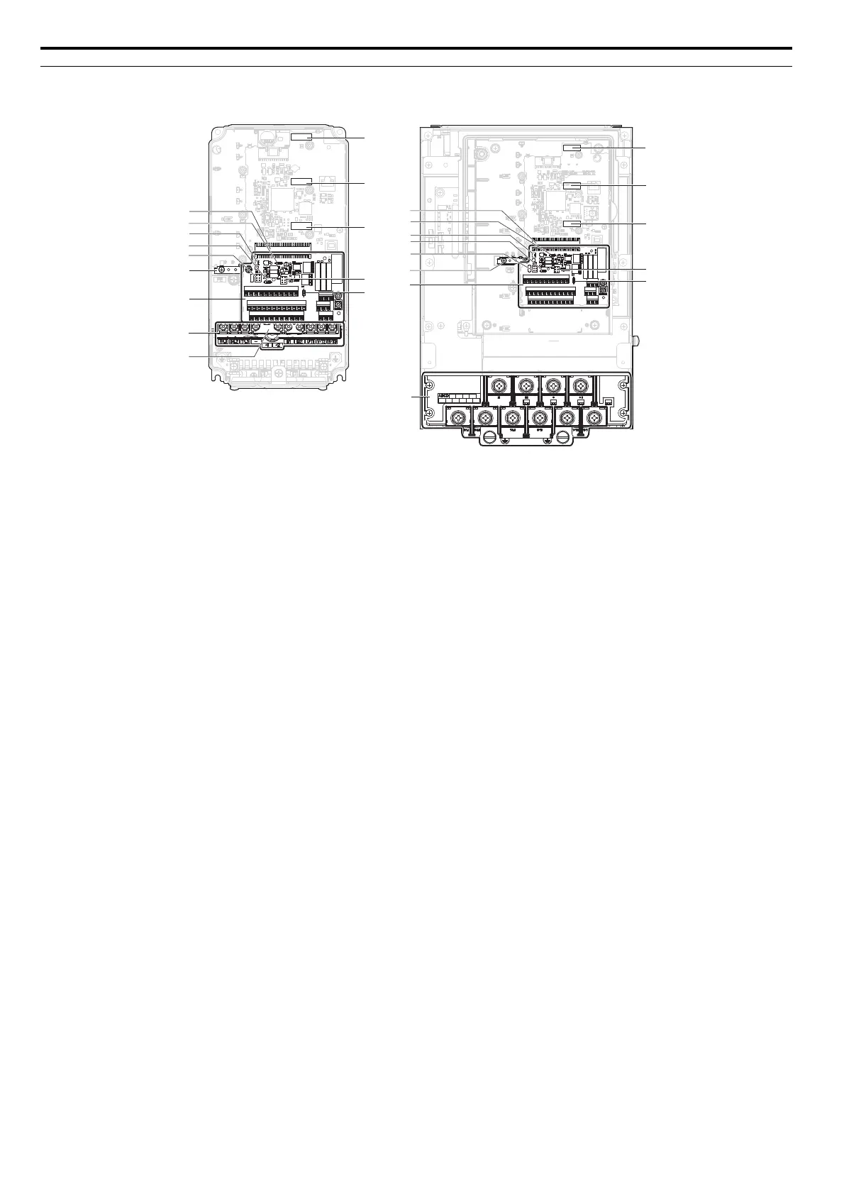
Front Views
Figure 1.9
Figure 1.9 Front View of Drives
A – Jumper S5 (Refer to Terminal AM/FM
Signal Selection on page 90)
H – DIP switch S2 (Refer to MEMOBUS/
Modbus Termination on page 91)
B – DIP Switch S4 (Refer to Terminal A3
Analog/PTC Input Selection on
page 90)
I – Slide switch S6 (Refer to Terminal
DM+ and DM- Output Signal Selection
on page 91)
C – Protecting cover to prevent miswiring J – DIP switch S1 (Refer to Terminal A2
Input Signal Selection on page 90)
D – Main circuit terminal (Refer to Wiring
the Main Circuit Terminal on page 82)
K – Terminal board connector
E – Terminal board (Refer to Control
Circuit Wiring on page 83)
L – Option card connector (CN5-C)
F – Ground terminal M – Option card connector (CN5-B)
G – Jumper S3 (Refer to Sinking/Sourcing
Mode Selection for Safe Disable
Inputs on page 88)
N – Option card connector (CN5-A)
K
L
N
M
C
D
E
F
J
CIMR-A2A0012F
H
I
G
K
D
E
F
J
H
I
G
N
M
L
CIMR-A2A0110A
A
B
A
B