4.7 Auto-Tuning
132 YASKAWA ELECTRIC SIEP C710616 27G YASKAWA AC Drive A1000 Technical Manual
T2-13: Induced Voltage Constant Unit Selection
Selects the units used for setting the induced voltage coefficient.
Setting 0: mV (min
-1
)
Setting 1: mV (rad/s)
Note: If T2-13 is set to 0, then the drive will use E5-24 (Motor Induction Voltage Constant 2 (for PM Motors)), and will automatically
set E5-09 (Motor Induction Voltage Constant 1 (for PM Motors)) to 0.0. If T2-13 is set to 1, then the drive will use E5-09 and
will automatically set E5-25 to 0.0.
T2-14: PM Motor Induced Voltage Constant (Ke)
Enter the motor induced voltage constant (Ke).
T2-15: Pull-In Current Level for PM Motor Tuning
Sets the amount of pull-in current used to tune the d-axis and q-axis inductance. Set as a percentage of the motor rated
current.
T2-16: PG Number of Pulses Per Revolution for PM Motor Tuning
Enter the number of pulses from the PG encoder per motor rotation. Set the actual number of pulses for one full motor
rotation.
T2-17: Encoder Z-Pulse Offset ()
Sets the amount of compensation or offset in 0.1 degree units in order to fine-tune the home position. If the amount of
offset needed for the Z pulse is unknown or if the PG encoder is replaced, perform Z pulse tuning.
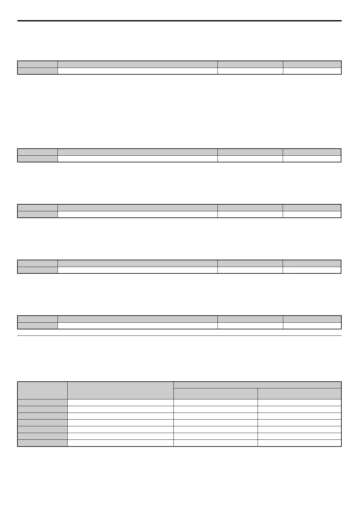
Parameter Settings during Inertia and Speed Control Loop Auto-Tuning: T3
These tuning methods apply a sine wave test signal to the system. By the measuring the response the drive estimates the
system inertia. It automatically sets parameters listed in Table 4.28.
Table 4.28 Parameters Adjusted by Inertia and Speed Loop Auto-Tuning
No. Name Setting Range Default
T2-13 Induced Voltage Constant Unit Selection 0, 1 1
No. Name Setting Range Default
T2-14 PM Motor Induced Voltage Constant 0.0 to 2000.0 Depending on T2-02
No. Name Setting Range Default
T2-15 Pull-In Current Level for PM Motor Tuning 0 to 120% 30%
No. Name Setting Range Default
T2-16 PG Number of Pulses Per Revolution for PM Motor Tuning 1 to 15000 ppr 1024 ppr
No. Name Setting Range Default
T2-17 Encoder Z-Pulse Offset -180.0 to 180.0 deg 0.0 deg
Parameter Description
T1-01 or T2-01
8
Inertia Tuning
9
Speed Control Loop (ASR) Tuning
C5-01 ASR Proportional Gain 1 N/A YES
C5-17 (C5-37) Motor Inertia YES YES
C5-18 (C5-38) Motor Inertia Ratio YES YES
L3-24 Motor Acceleration Time for Inertia Calculations YES YES
L3-25 Load Inertia Ratio YES YES
n5-02 Motor Acceleration Time YES YES
n5-03 Feed Forward Control Ratio Gain YES YES