3.5 Terminal Cover
YASKAWA ELECTRIC SIEP C710616 27G YASKAWA AC Drive A1000 Technical Manual 68
3.5 Terminal Cover
Follow the procedure below to remove the terminal cover for wiring and to reattach the terminal cover after wiring is
complete.
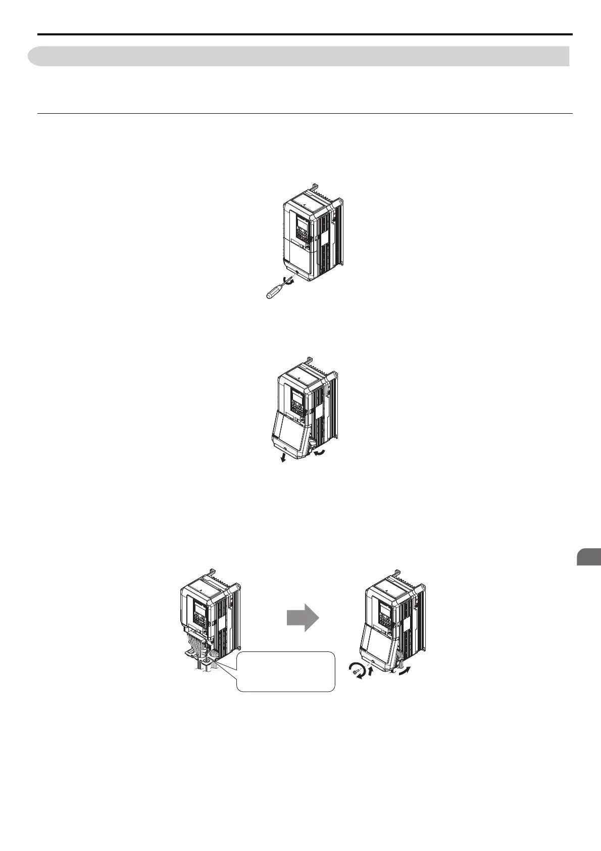
CIMR-A2A0004 to 0081, 4A0002 to 0044 (IP20/NEMA 1, UL Type 1 Enclosure)
Removing the Terminal Cover
1. Loosen the terminal cover screw.
Figure 3.8
Figure 3.5 Removing the Terminal Cover on an IP20/NEMA 1, UL Type 1 Enclosure Drive
2. Push in on the hook located on the bottom of the terminal cover, and gently pull forward. This should remove the
terminal cover.
Figure 3.9
Figure 3.6 Removing the Terminal Cover on an IP20/NEMA 1, UL Type 1 Enclosure Drive
Reattaching the Terminal Cover
Power lines and signal wiring should pass through the opening provided. Refer to Wiring the Main Circuit Terminal on
page 82 and Wiring the Control Circuit Terminal on page 85 for details on wiring.
After all wiring to the drive and other devices is complete, reattach the t
erminal cover.
Figure 3.10
Figure 3.7 Reattaching the Terminal Cover on an IP20/NEMA 1, UL Type 1 Enclosure Drive
Connect ground wiring first,
followed by the main circuit,
and then wire the control circuit.
Power lines and signal wiring
exit through the opening provided.