5.7 H: Terminal Functions
246 YASKAWA ELECTRIC SIEP C710616 27G YASKAWA AC Drive A1000 Technical Manual
H2: Multi-Function Digital Outputs
H2-01 to H2-03: Terminal M1-M2, M3-M4, and M5-M6 Function Selection
The drive has three multi-function output terminals. Table 5.40 lists the functions available for theses terminals using
H2-01, H2-02, and H2-03.
Table 5.40 Multi-Function Digital Output Terminal Settings
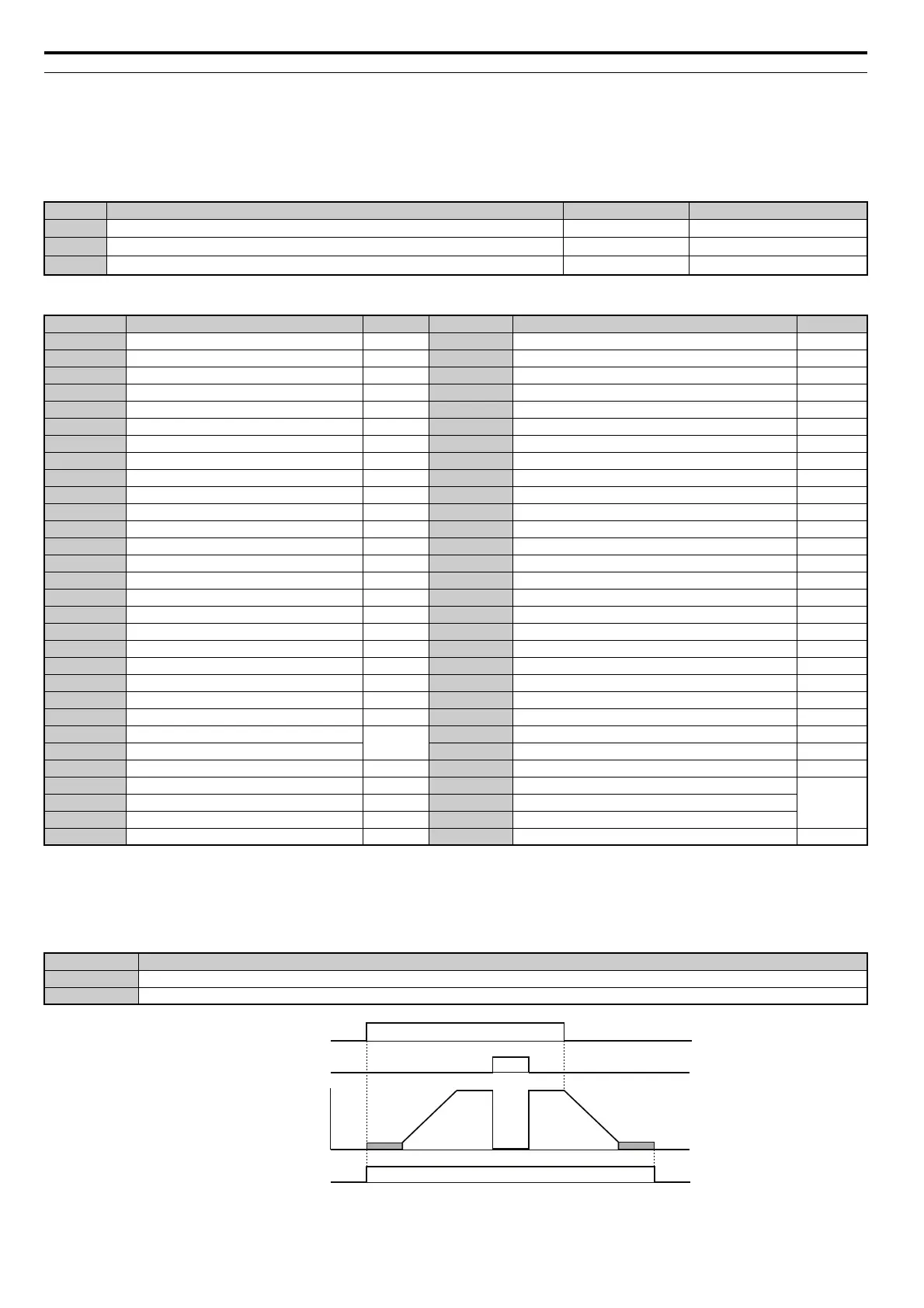
Setting 0: During Run
Output closes when the drive is outputting a voltage.
Figure 5.68
Figure 5.68 During Run Time Chart
No. Parameter Name Setting Range Default
H2-01
Terminal M1-M2 Function Selection
0 to 192 0: During run
H2-02
Terminal M3-M4 Function Selection
0 to 192 1: Zero Speed
H2-03
Terminal M5-M6 Function Selection
0 to 192 2: Speed agree 1
Setting Function Page Setting Function Page
0
<1> Not available in models CIMR-A4A0930 and 4A1200.
<2> Not available in models CIMR-A2A0169 to 2A0415 and 4A0088 to 4A1200.
During run 246 1E Restart enabled 253
1 Zero Speed 247 1F Motor overload alarm (oL1) 253
2 Speed agree 1 247 20 Drive overheat pre-alarm (oH) 253
3 User-set speed agree 1 248 22 Mechanical Weakening detection 253
4 Frequency detection 1 248 2F Maintenance period 254
5 Frequency detection 2 249 30 During torque limit 254
6 Drive ready 249 31 During speed limit 254
7 DC bus undervoltage 249 32 During speed limit in Torque Control 254
8 During baseblock (N.O.) 249 33 Zero Servo complete 254
9 Frequency reference source 249 37 During frequency output 254
A Run command source 250 38 Drive enabled 254
B Torque detection 1 (N.O.) 250 39 Watt hour pulse output 254
C Frequency reference loss 250 3C LOCAL/REMOTE Status 255
D <1> Braking resistor fault 250 3D During Speed Search 255
E Fault 250 3E PID feedback low 255
F Through mode 250 3F PID feedback high 255
10 Minor fault 250 4A During KEB operation 255
11 Fault reset command active 250 4B During Short Circuit Braking 255
12 Timer output 250 4C During Fast Stop 255
13 Speed agree 2 251 4D oH pre-alarm time limit 255
14 User-set speed agree 2 251 4E <2> Braking transistor fault (rr) 255
15 Frequency detection 3 252 4F <2> Braking resistor overheat (rH) 255
16 Frequency detection 4 252 60 Internal cooling fan alarm 255
17 Torque detection 1 (N.C.)
250
61 Rotor Position Detection Completed 255
18 Torque detection 2 (N.O.) 62 <1> Memobus Regs1 (It selects it with H2-07 and H2-08.) 255
19 Torque detection 2 (N.C.) 250 63 <1> Memobus Regs2 (It selects it with H2-09 and H2-10.) 255
1A During reverse 253 90 DriveWorksEZ digital output 1
255
1B During baseblock (N.C.) 253 91 DriveWorksEZ digital output 2
1C Motor 2 selection 253 92 DriveWorksEZ digital output 3
1D During regeneration 253 100 to 192 Functions 0 to 92 with inverse output 256
Status Description
Open Drive is stopped.
Closed A Run command is input or the drive is during deceleration or during DC injection.
ON
ON
OFF
OFF
ONOFF
Run command
Baseblock
command
Output
frequency
During Run