5.7 H: Terminal Functions
YASKAWA ELECTRIC SIEP C710616 27G YASKAWA AC Drive A1000 Technical Manual 245
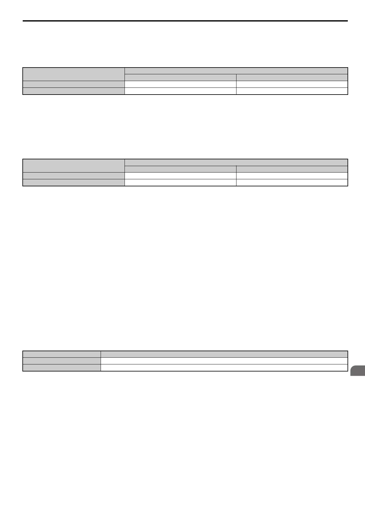
Setting 7A, 7B: KEB Ride-Thru 2 (N.C., N.O.)
An input terminal set to 7A or 7B can trigger Single Drive KEB Ride-Thru during deceleration. If enabled, L2-29 is
disregarded. Refer to KEB Ride-Thru Function on page 275 for details.
Note: KEB Ride-Thru 1 and 2 cannot both be assigned to the input terminals at the same time. Doing so will trigger an oPE3 error.
Setting 7C, 7D: Short Circuit Braking (N.O., N.C.) (OLV/PM, AOLV/PM)
An input programmed for this function can be used to activate Short Circuit Braking in Open Loop Vector control modes
for PM motors. By linking all three phases of a PM motor, Short Circuit Braking creates a braking torque that can be used
to stop a rotating motor or prevent a motor from coasting due to external forces (such as the windmill effect in fan
applications). Parameter b2-18 can be used to limit the current during Short Circuit Braking.
Setting 7E: Forward/reverse detection
Determines the motor rotation direction for V/f Control with Simple PG feedback or V/f Control with PG feedback when
F1-21 (PG 1 Signal Selection) or F1-37 (PG 2 Signal Selection) are set to 0 (A Pulse Detection).
If the input is open, the speed feedback signal is cons
idered to be forward. If the input is closed, it is considered to be in
reverse. Refer to H6: Pulse Train Input/Output on page 264.
Setting 7F: Bi-Directional PID Output Selection
If PID output to bi-directional output conversion is enabled in parameter d4-11, a digital input programmed for 7F can be
used to switch between normal output or bi-directional output. If the digital input is open, the PID output builds the out-
put frequency reference.
If the input is closed, the PID output is converted to bi-directional
output frequency reference. Refer to d4-11:
Bi-Directional Output Selection on page 206.
Setting 90 to 97: DriveWorksEZ Digital Input 1 to 8
These settings are for digital inputs functions used in DriveWorksEZ. Normally there is no need to change these settings.
Setting 9F: DriveWorksEZ Disable
This function is used to enable or disable a DriveWorksEZ program in the drive. An input programmed for this function
is effective only if A1-07 = 2.
Digital Input Function
Drive Operation
Input Open Input Closed
Setting 7A (N.C.) Single Drive KEB Ride-Thru 2 Normal operation
Setting 7B (N.O.) Normal operation Single Drive KEB Ride-Thru 2
DIgital Input Function
Drive Operation
Input Open Input Closed
Setting 7C (N.O.) Normal operation Short Circuit Braking
Setting 7D (N.C.) Short-Circuit Braking Normal operation
Status Description
Open DriveWorksEZ enabled
Closed DriveWorksEZ disabled