5.2 b: Application
158 YASKAWA ELECTRIC SIEP C710616 27G YASKAWA AC Drive A1000 Technical Manual
b2: DC Injection Braking and Short Circuit Braking
These parameters determine how the DC Injection Braking, Zero Speed Control, and Short Circuit Braking features
operate.
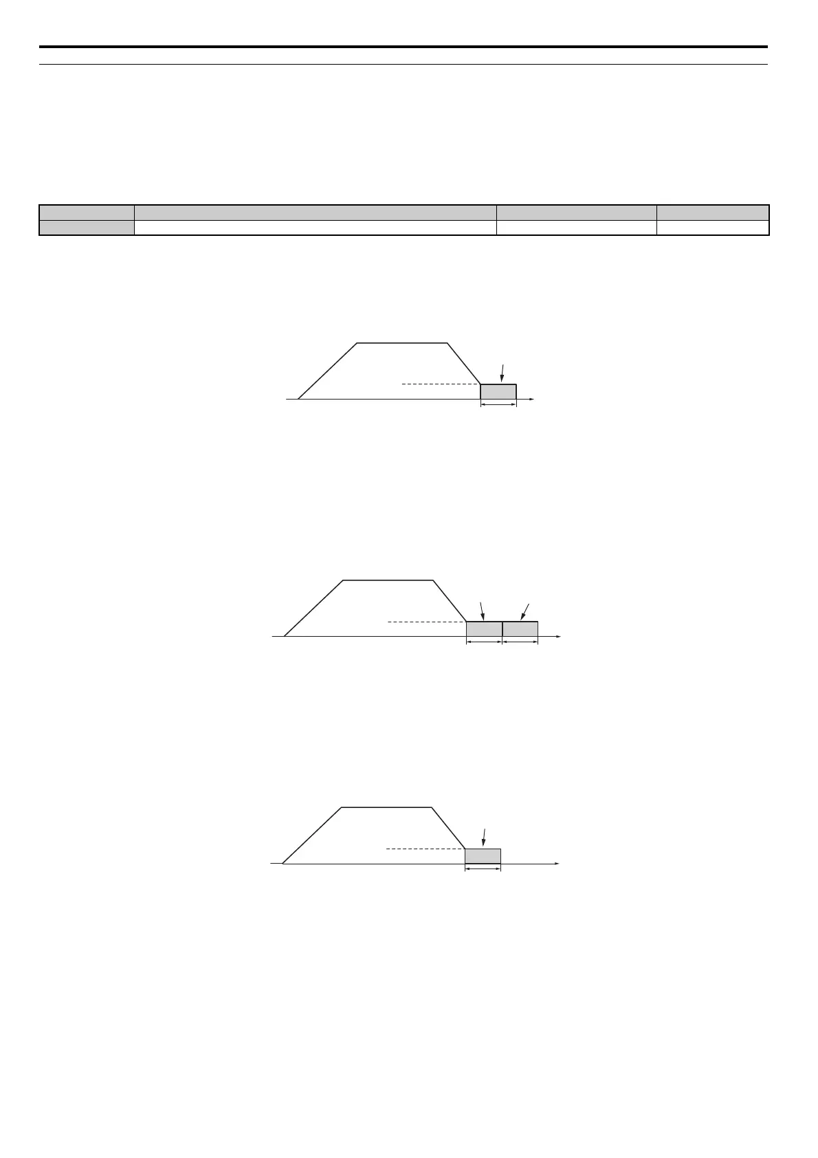
b2-01: DC Injection Braking Start Frequency
Parameter b2-01 is active when “Ramp to stop” is selected as the stopping method (b1-03 = 0).
The function triggered by parameter b2-01 depends on the control mode that has been selected.
V/f, V/f w/PG and OLV (A1-02 = 0, 1, 2)
For these control modes, parameter b2-01 sets the starting frequency for DC Injection Braking at stop. Once the output
frequency falls below the setting of b2-01, DC Injection Braking is enabled for the time set in parameter b2-04.
Figure 5.16
Figure 5.16 DC Injection Braking at Stop for V/f, V/f w/PG and OLV
Note: If
b2-01 is set to a smaller value than parameter E1-09 (minimum frequency), then DC Injection Braking will begin as soon as
the frequency falls to the value set to E1-09.
OLV/PM and AOLV/PM (A1-02 = 5, 6)
For these control modes, parameter b2-01 sets the starting frequency for Short-Circuit Braking at stop. Once the output
frequency falls below the setting of b2-01, Short-Circuit Braking is enabled for the time set in parameter b2-13. If DC
Injection Braking time is enabled at stop, then DC Injection Braking is performed for the time set in b2-04 after
Short-Circuit Braking is complete.
Figure 5.17
Figure 5.17 Short-Circuit Braking at Stop in OLV/PM and AOLV/PM
Note: If
b2-01 is set to a smaller value than parameter E1-09 (minimum frequency), then DC Injection Braking will begin as soon as
the frequency falls to the value set to E1-09.
CLV and CLV/PM (A1-02 = 3, 7)
For these control modes, parameter b2-01 sets the starting frequency for Zero Speed Control (not position lock) at stop.
Once the output frequency falls below the setting of b2-01, Zero Speed Control is enabled for the time set in parameter
b2-04.
Figure 5.18
Figure 5.18 Zero Speed Control at Stop in CLV and CLV/PM
Note: If
b2-01 is set to lower than the minimum frequency (E1-09), then Zero Speed Control begins at the frequency set to E1-09.
No. Name Setting Range Default
b2-01 DC Injection Braking Start Frequency 0.0 to 10.0 Hz Determined by A1-02
Output
frequency
Time
b2-04
DC Injection
Braking
E1-09 Min. Frequency
b2-01 Zero Speed Level
Output
frequency
Time
DC Injection
Braking
b2-04b2-13
Short Circuit
Braking
E1-09 Min. Frequency
b2-01 Zero Speed Level
Output
frequency
Time
Zero Speed
Control
b2-04
E1-09 Min. Frequency
b2-01 Zero Speed Level