5.6 F: Option Settings
230 YASKAWA ELECTRIC SIEP C710616 27G YASKAWA AC Drive A1000 Technical Manual
F4: Analog Monitor Card Settings
These parameters set up the drive for operation with the analog output option card AO-A3. This section describes
parameters that govern operation with an analog output option card. Refer to the instruction manual packaged with the
option card for specific details on installation, wiring, input signal level selection, and parameter setup.
F4-01, F4-03: Terminal V1, V2 Monitor Selection
Selects the data to output from analog terminal V1. Enter the final three digits of U- to determine which monitor
data is output from the option card. Some monitors are only available in certain control modes.
Note: Set “000” or “031” when using the terminal in through mode. This setting can adjust the V1 and V2 terminal output from PLC
via MEMOBUS/Modbus communications or a communications option.
F4-02, F4-04, F4-05, F4-06: Terminal V1, V2 Monitor Gain and Bias
Parameters F4-02 and F4-04 determine the gain, while parameters F4-05 and F4-06 set the bias. These parameters are set
as a percentage of the output signal from V1 and V2 where 100% equals 10 V output. The terminal output voltage is
limited to 10 V.
Using Gain and Bias to Adjust Output Signal Level
The output signal is adjustable while the drive is stopped.
Terminal V1
1. View the value set to F4-02 (Terminal V1 Monitor Gain) on the digital operator. A voltage equal to 100% of the
parameter being set in F4-01 will be output from terminal V1.
2. Adjust F4-02 viewing the monitor connected to the
terminal V1.
3. View the value set to F4-05 on the digital
operator, terminal V1 will output a voltage equal to 0% of the parameter
being set in F4-01.
Adjust F4-05 viewing the output signal on the
terminal V1.
Terminal V2
1. View the value set to F4-02 (Terminal V2 Monitor Gain) on the digital operator. A voltage equal to 100% of the
parameter being viewed in F4-03 will be output from terminal V2.
2. Adjust F4-04 viewing the monitor connected to the
terminal V2.
3. View the value set to F4-06 on the digital
operator, terminal V2 will output a voltage equal to 0% of the parameter
being set in F4-03.
4. Adjust F4-06 viewing the output signal on the
terminal V2.
F4-07, F4-08: Terminal V1, V2 Signal Level
Sets the output signal level for terminals V1 and V2.
Setting 0: 0 to 10 V
Setting 1: -10 to 10 V
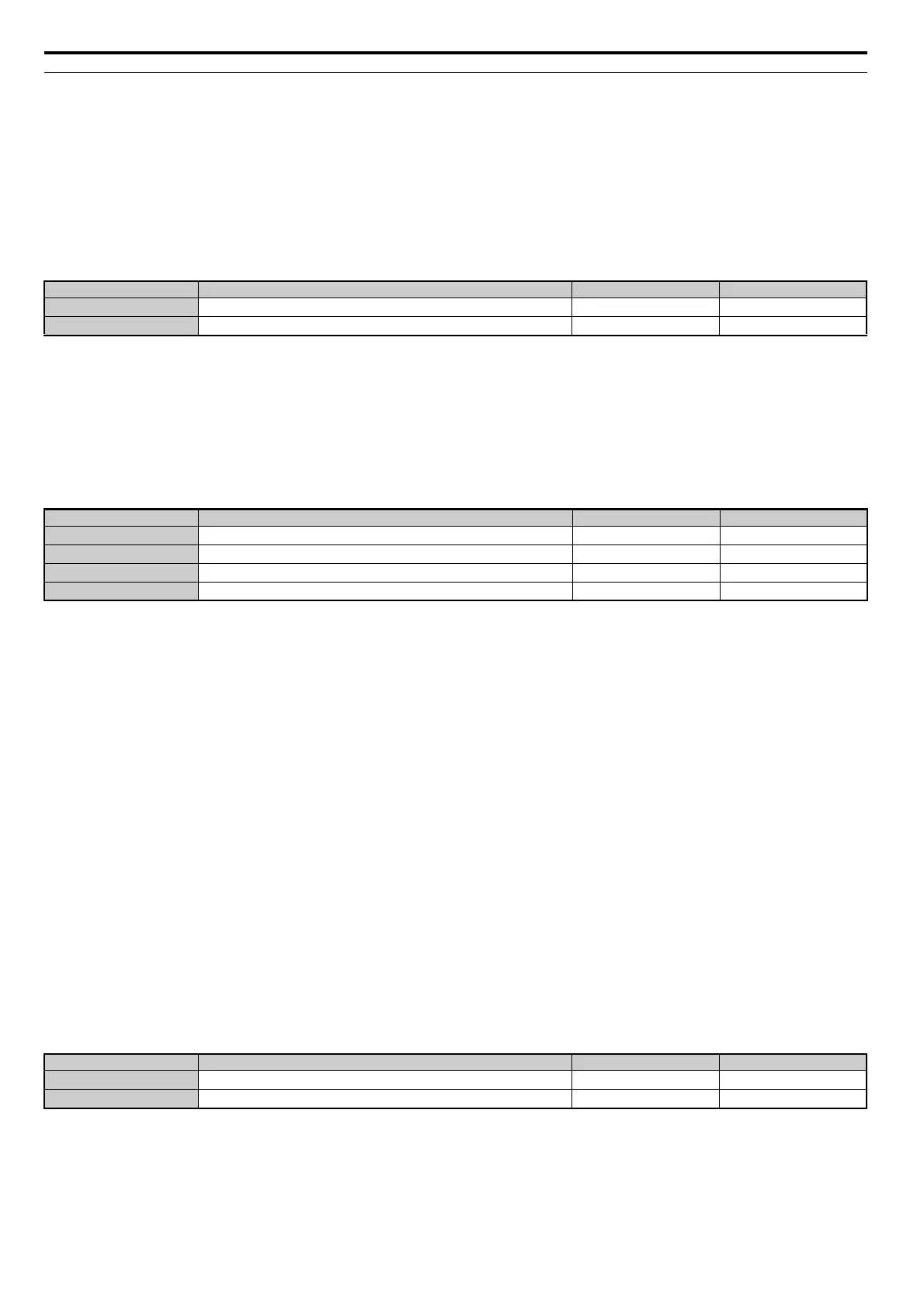
No. Parameter Name Setting Range Default
F4-01
Terminal V1 Monitor Selection
000 to 999 102
F4-03
Terminal V2 Monitor Selection
000 to 999 103
No. Parameter Name Setting Range Default
F4-02
Terminal V1 Monitor Gain
-999.9 to 999.9% 100.0%
F4-04
Terminal V2 Monitor Gain
-999.9 to 999.9% 50.0%
F4-05
Terminal V1 Monitor Bias
-999.9 to 999.9% 0.0%
F4-06
Terminal V2 Monitor Bias
-999.9 to 999.9% 0.0%
No. Parameter Name Setting Range Default
F4-07
Terminal V1 Signal Level
0, 1 0
F4-08
Terminal V2 Signal Level
0, 1 0