5.8 L: Protection Functions
288 YASKAWA ELECTRIC SIEP C710616 27G YASKAWA AC Drive A1000 Technical Manual
L3-26: Additional DC Bus Capacitors
Sets the capacity of any additional DC bus capacitors that have been installed. This data is used in calculations for Single
Drive KEB Ride-Thru 2. This setting needs to be adjusted only if external capacity is connected to the drives DC bus and
Single Drive KEB 2 is used.
L3-27: Stall Prevention Detection Time
Sets a delay time from when the Stall Prevention level is reached and the actual Stall Prevention function is activated.
L3-34: Torque Limit Delay Time
Sets the filter time constant in seconds for the torque limit value to return to set value when the Power KEB Ride-Thru is
enabled (L2-29 = 1). If oscillation occurs during Power KEB Ride-Thru, then gradually increase this setting in
increments of 0.010 s.
Note: This parameter is not available in models CIMR-A4A0930 and 4A1200.
L3-35: Speed Agree Width at Intelligent Stall Prevention during Deceleration
There is normally no need to change this parameter from the default value.
Sets the speed agreement width when L3-04 = 2 (Intell
igent Stall Prevention during deceleration) in unit of 0.01 Hz. Use
this parameter when hunting is started by a frequency reference in analog input.
Note: This parameter is not available in models CIMR-A4A0930 and 4A1200.
L4: Speed Detection
These parameters set up the speed agree and speed detection functions which can be assigned to the multi-function
output terminals.
The speed is detected using the motor speed when A1-02 = 3 or 7.
L4-01, L4-02: Speed Agreement Detection Level and Detection Width
Parameter L4-01 sets the detection level for the digital output functions “Speed agree 1,” “User-set speed agree 1,”
“Frequency detection 1,” and “Frequency detection 2.”
Parameter L4-02 sets the hysteresis level for these functions.
Refer to H2-01 to H2-03: Terminal M1-M2, M3-M4, and M5-M6 Function Selection on page 246, Settings 2, 3, 4, and
5.
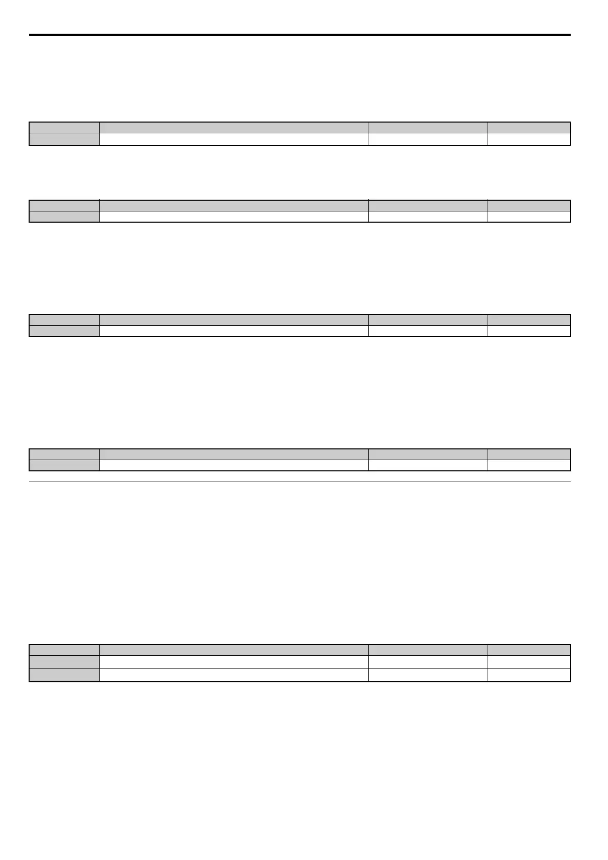
No. Name Setting Range Default
L3-26 Additional DC Bus Capacitors 0 to 65000 F
0
F
No. Name Setting Range Default
L3-27 Stall Prevention Detection Time 0 to 5000 ms 50 ms
No. Name Setting Range Default
L3-34
<1> L3-34 = 0.200 when A1-02 = 6, L3-34 = 0.020 when A1-02 = 7.
Torque Limit Delay Time 0.000 to 1.000 s Determined by A1-02 <1>
No. Name Setting Range Default
L3-35 Speed Agree Width at Intelligent Stall Prevention during Deceleration 0.00 to 1.00 Hz 0.00 Hz
No. Name Setting Range Default
L4-01
<1> In AOLV/PM and CLV/PM control modes, the setting units and range are expressed as a percent (0.0 to 100.0%) instead of in Hz.
Speed Agreement Detection Level
0.0 to 400.0 Hz
<1> 0.0 Hz <1>
L4-02
Speed Agreement Detection Width
0.0 to 20.0 Hz Determined by A1-02