6.6 Operator Programming Errors
YASKAWA ELECTRIC SIEP C710616 27G YASKAWA AC Drive A1000 Technical Manual 359
Causes and Possible Solutions for a Blank and Unresponsive Digital Operator
Table 6.18 Causes and Possible Solutions for a Blank and Unresponsive Digital Operator
Digital Operator Display Error Name
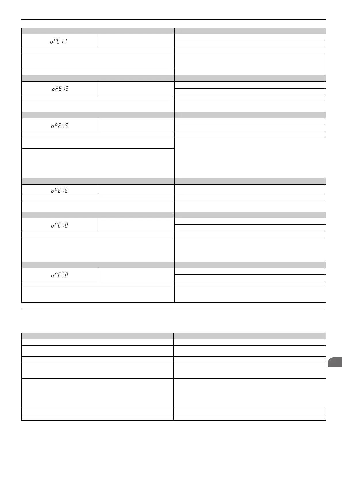
oPE11
Carrier Frequency Setting Error
Corre
ct the setting for the carrier frequency.
Cause Possible Solutions
The following simultaneous contradictory settings: C6-05 is greater than 6 and C6-04 is
greater than C6-03 (carrier frequency lower limit is greater than the upper limit). If C6-05 is
less than or equal to 6, the drive operates at C6-03.
Correct the parameter settings.
Upper and lower limits between C6-02 and C6-05 contradict each other.
Digital Operator Display Error Name
oPE13
Pulse Monitor Selection Error
Incorrect
setting of monitor selection for pulse train (H6-06).
Cause Possible Solutions
Scaling for the pulse train monitor is set to 0 (H6-07 = 0) while H6-06 is not set to 101, 102,
105, or 116.
Change scaling for the pulse train monitor or set H6-06 to 101, 102, 105, or 116.
Digital Operator Display Error Name
oPE15
Torque Control Setting Error
P
arameters settings that are not allowed in combination with Torque Control have been set.
Cause Possible Solutions
Torque Control in enabled (d5-01 = 1) while the Speed/T
orque Control switch function is
assigned to a digital input (H1- = 71).
Correct the parameter settings.
Either Torque Control is enabled by d5-01 = 1, the or Speed/Torque Control switch is assigned
to a digital input H1- = 71, while at the same time:
• Feed Forward is enabled (n5-01 = 1), or
• Droop Control is enabled (b7-01 0), o
r
• Intelligent Stall Prevention or Intelligent Stall
Prevention 2 is enabled (L3-04 = 2 or 5), or
• A digital input is set for the power KEB 1 or KEB 2 (H1-
= 7A or 7B)
Digital Operator Display Error Name
oPE16 Energy Savings Constants Error
Cause Possible Solutions
In AOLV/PM the automatically calculated energy saving coefficients are out of the allowable
range.
Check and correct the motor data in E5 parameters.
Digital Operator Display Error Name
oPE18
Online Tuning Parameter Setting Error
Param
eters that control Online Tuning are not set correctly.
Cause Possible Solutions
One of the following setting errors has occurred whi
le Online Tuning is enabled in OLV
(A1-02 = 2):
• E2-02 has been set below 30% of the ori
ginal default value
• E2-06 has been set below 50% of the ori
ginal default value
• E2-03 = 0
Make sure E2-02, E2-03, and E2-06 are set the correct values.
Digital Operator Display Error Name
oPE20
PG-F3 Setting Error
The encoder si
gnal frequency is too high.
Cause Possible Solutions
With the entered encoder resolution (F1-01), m
aximum output frequency (E1-04), and motor
pole number (E5-04,) the calculation encoder signal frequency exceeds 50 kHz (with PG-F3
option).
• Set F1-01 to the correct encoder resolution.
• Reduce the maximum output frequency of the drive in parameter E1-04 so the encoder
s
ignal frequency at maximum speed is lower than 50 kHz.
Cause Possible Solutions
A short circuit between +V, -V, and AC terminals. Correct wiring
Control circuit terminal overload.
Check the resistance and wiring for the frequency setting potentiometer, etc.
Check that the current for terminals +V and -V is 20 mA or less.
The short circuit bar between terminals +1 and +2 in the main circuit has been removed. Attach the short circuit bar.
Braking unit terminals P and N are connected in reverse.
• Check the Braking unit wiring including cables connected to the Braking unit and relay
terminals.
• Replace the drive.
Control power circuit failure
C
harge indicator is lit:
• Replace the digital operator
• Replace the drive control board.
Charge indicator is not lit:
• Check the input power supply voltage
• Replace the drive.
Malfunction occurred in the control power circuit. Turn OFF t
he power, wait for 5 minutes, then turn ON the power again.
Digital operator contact failure Turn OFF the power, remove the digital operator, then replace the digital operator.