114 YASKAWA ELECTRIC SIEP C710616 27G YASKAWA AC Drive A1000 Technical Manual
4.6 Application Selection
4.6 Application Selection
Several Application Presets are available to facilitate drive setup for commonly used applications. Selecting one of these
Application Presets automatically assigns functions to the input and output terminals, and sets certain parameters to
values appropriate for the application that was selected. In addition, the parameters most likely to be changed are
assigned to the group of User Parameters, A2-01 through A2-16. User Parameters are part of the Setup Group, and
provide quicker access to by eliminating the need to scroll through multiple menus.
An Application Preset can either be selected from the Application Select
ion display in the Setup Group (Refer to
Simplified Setup Using the Setup Group on page 107) or in parameter A1-06. The following prese
ts can be selected:
Note: 1. An Application Preset can only be selected if all drive parameters are on at their original default settings. It may be necessary to
initialize the drive by setting A1-03 to “2220” or “3330” prior to selecting an Application Preset.
2. Do not
set any value outside the allowable range for A1-06 (Application Presets). If an out-of-range value is set, “APPL” will be
displayed flashing in the Setup group and the up and down arrow keys cannot be used. If this happens, press the ESC key to return to
the Setup group. It will then be possible to switch to another mode using the up and down arrow keys. Setting values to A1-06 out of
the setting range will not affect drive operation, however.
3. The
values set for A1-06 cannot be changed except by initializing the values by setting A1-03=2220, and then making new settings.
If you will encounter a problem if all of the parameters are initialized, the setting of A1-06 does not need to be changed.
WARNING! Confirm th
e drive I/O signals and external sequence before performing a test run. Setting parameter A1-06 may change
the I/O terminal function automatically from the default setting. Failure to comply may result in death or serious injury.
Table 4.5 Application Presets (A1-06)
Setting 1: Water Supply Pump Application
Table 4.6 Water Supply Pump: Parameter Settings
Table 4.7 Water Supply Pump: User P
arameters (A2-01 to A2-16)
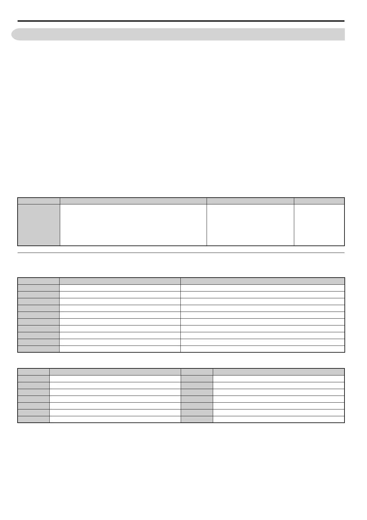
No. Parameter Name Setting Range Default
A1-06
Application Presets
0: Disabled
1: Water supply pump
2: Conveyor
3: Exhaust fan
4: HVAC
5: Compressor
6: Hoist
7: Crane
0
No. Name Default Setting
A1-02 Control Method Selection 0: V/f Control
b1-04 Reverse Operation Selection 1: Reverse Prohibited
C1-01 Acceleration Time 1 1.0 s
C1-02 Deceleration Time 1 1.0 s
C6-01 Duty Rating 1: Normal Duty (ND)
E1-03 V/f Pattern Selection F: V/f Pattern Selection
E1-07 Mid Output Frequency 30.0 Hz
E1-08 Mid Output Frequency Voltage 50.0 V
L2-01 Momentary Power Loss Operation Selection 1: Enabled
L3-04 Stall Prevention Selection during Deceleration 1: Enabled
No. Parameter Name No. Parameter Name
b1-01 Frequency Reference Selection E1-08 Mid Output Frequency Voltage
b1-02 Run Command Selection E2-01 Motor Rated Current
b1-04 Reverse Operation Selection H1-05 Multi-Function Digital Input Terminal S5 Function Selection
C1-01 Acceleration Time 1 H1-06 Multi-Function Digital Input Terminal S6 Function Selection
C1-02 Deceleration Time 1 H1-07 Multi-Function Digital Input Terminal S7 Function Selection
E1-03 V/f Pattern Selection L5-01 Number of Auto Restart Attempts
E1-07 Mid Output Frequency