360 YASKAWA ELECTRIC SIEP C710616 27G YASKAWA AC Drive A1000 Technical Manual
6.7 Auto-Tuning Fault Detection
6.7 Auto-Tuning Fault Detection
Auto-Tuning faults in this section are displayed on the digital operator and will cause the motor to coast to a stop.
Auto-tuning faults do not trigger a multi-function digital output set for fault or alarm output.
An (End) error on the digital operator display indicates Auto-Tuning has succes
sfully completed with discrepancies in
the calculations. Check the cause of the (End) error using the tables in this sect
ion and perform Auto-Tuning again
after fixing the cause.
The drive may be used in the applicat
ion if no cause can be identified despite the existence of an (End) error.
An (Er-) error indicates that Auto-Tuning has not completed suc
cessfully. Check for the cause of the error using the
tables in this section, and perform Auto-Tuning again after fixing the cause.
Auto-Tuning Codes, Causes, and Possible Solutions
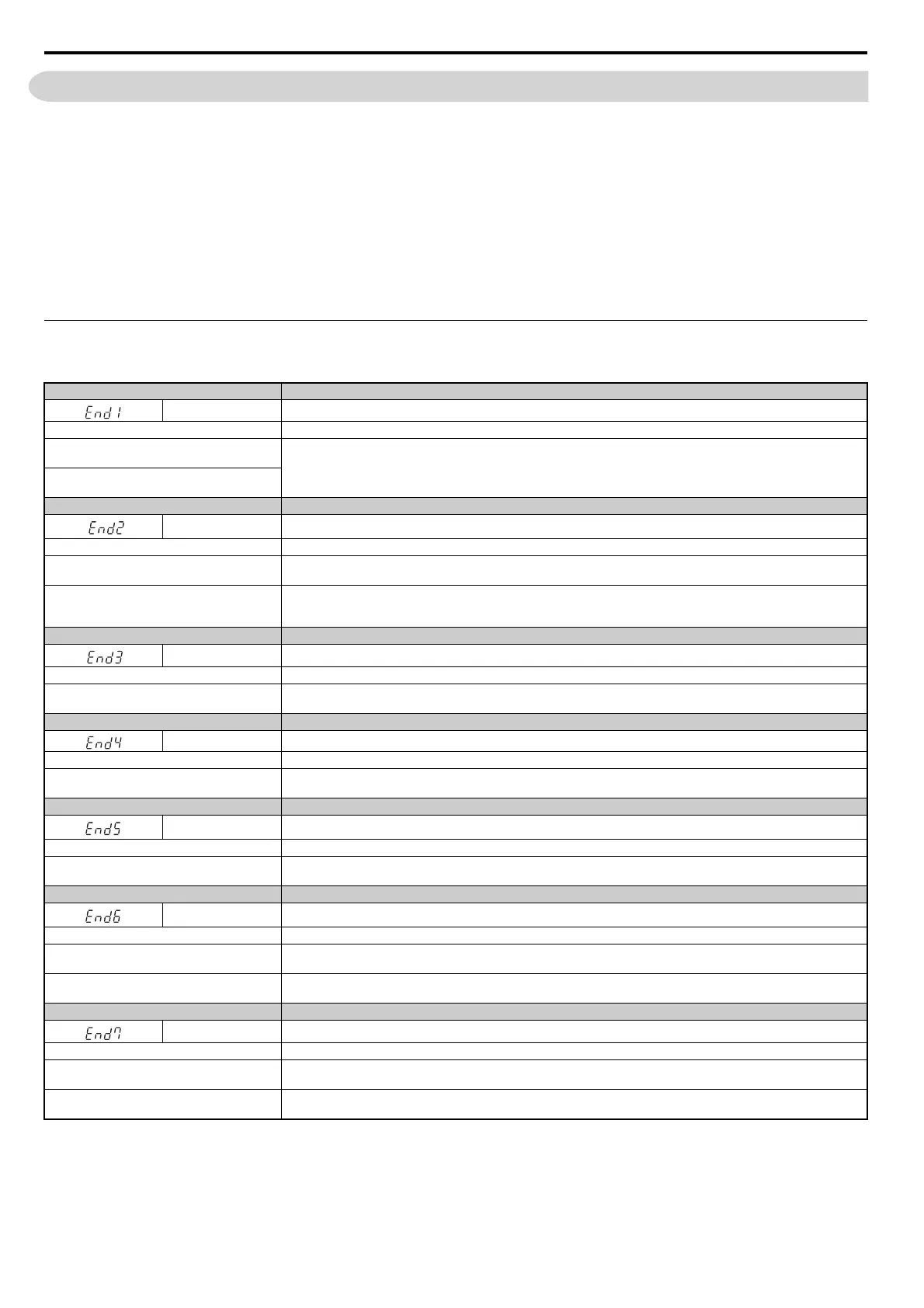
Table 6.19 Auto-Tuning Codes, Causes, and Possible Solutions
Digital Operator Display Error Name
End1
Excessive V/f Setting (detected only durin
g Rotational Auto-Tuning, and displayed after Auto-Tuning is complete)
Cause Possible Solutions
The torque reference exceeded 20% during
Aut
o-Tuning.
• Before Auto-Tuning the drive, verify the information written on t
he motor nameplate and enter that data to T1-03 through T1-05.
• Enter proper information to parameters
T1-03 to T1-05 and repeat Auto-Tuning.
• If possible, disconnect the motor from the load and perform Auto
-Tuning. If the load cannot be uncoupled, simply use the
Auto-Tuning results as they are.
The results from Auto-Tuning the no-load current
exceeded 80%.
Digital Operator Display Error Name
End2
Motor Iron-Core Saturation Coefficient (detected only during Rotat
ional Auto-Tuning and displayed after Auto-Tuning is complete)
Cause Possible Solutions
Motor data entered during Auto-Tuning was
in
correct.
• Make sure the data entered to the T1 parameters match the information written on the motor nameplate.
• Restart Auto-Tuning and enter the correct information.
Results from Auto-Tuning are outside the parameter
s
etting range, assigning the iron-core saturation
coefficient (E2-07, E2-08) a temporary value.
• Check and correct faulty motor wiring.
• Disconnect the motor from machine and perform Rotational Auto-Tuning.
Digital Operator Display Error Name
End3
Rated Current Setting Alarm (displayed after Auto-Tuning is complete)
Cause Possible Solutions
The correct current rating printed on the nameplate
wa
s not entered into T1-04.
• Check the setting of parameter T1-04.
• Check the motor data and repeat Auto-Tuning.
Digital Operator Display Error Name
End4 Adjusted Slip Calculation Error
Cause Possible Solutions
The slip that was calculated is outside the allowable
ra
nge.
• Make sure the data entered for Auto-Tuning is correct.
• Execute Rotational Auto-Tuning instead. If not possible, try Stationary Auto-Tuning 2.
Digital Operator Display Error Name
End5 Resistance Tuning Error
Cause Possible Solutions
The resistance value that was calculated is outside
th
e allowable range.
• Double check the data that was entered for the Auto-Tuning process.
• Check the motor and motor cable connection for faults.
Digital Operator Display Error Name
End6 Leakage Inductance Alarm
Cause Possible Solutions
A1-02 setting error
• Check the setting of parameter A1-02.
• Check the control mode and repeat Auto-Tuning.
The leakage inductance value that was calculated is
outside the allowable range.
Double check the data that was entered for the Auto-Tuning process.
Digital Operator Display Error Name
End7 No-Load Current Alarm
Cause Possible Solutions
The entered no-load current value was outside the
al
lowable range.
Check and correct faulty motor wiring.
Auto-Tuning results were less than 5% of the motor
rated current.
Double check the data that was entered for the Auto-Tuning process.