5.5 E: Motor Parameters
220 YASKAWA ELECTRIC SIEP C710616 27G YASKAWA AC Drive A1000 Technical Manual
E3-04 to E3-13
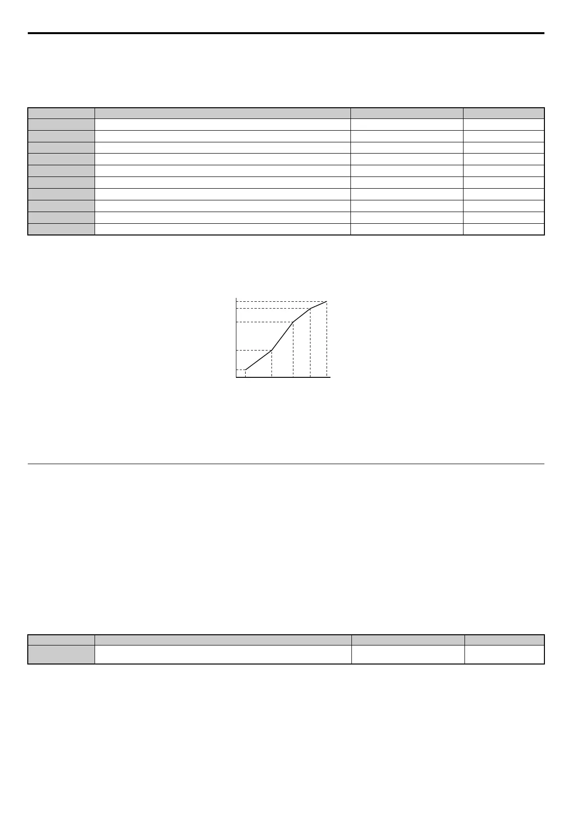
Parameters E3-04 through E3-13 set up the V/f pattern used for motor 2 as shown in Figure 5.57.
Note: Certain E3- parameters might not be visible depending on the control mode. Refer to Parameter Table on page 453.
Figure 5.57
Figure 5.57 V/f Pattern for Motor 2
Note: 1. The following
conditions must be true when setting up the V/f pattern: E3-09 E3-07 E3-06 E3-11 E3-04
2. T
o make the V/f pattern a straight line at a frequency lower than E3-06, set E3-09 = E3-07. With this setting, E3-08 is disregarded.
3. Parameters E3-04 through E3-13 are reset to their default values when the drive is initialized.
4. E3-11, E3-12, and E3-13 rarely need to be changed, and should only be used to fine-tune the V/f pattern in the constant output range.
E4: Motor 2 Parameters
E4 parameters contain the motor data for motor 2. These parameters are usually set automatically during the
Auto-Tuning process (Rotational Auto-Tuning, Stationary Auto-Tuning 1 and 2). If Auto-Tuning cannot be performed,
refer to Auto-Tuning Fault Detection on page 360 for detail.
Note: As the function for switching between two motors cannot be used with a PM motor, the E5- parameters will be hidden when
a PM motor control mode is selected (A1-02 = 5, 6, or 7).
E4-01: Motor 2 Rated Current
Set E4-01 to the full load amps (FLA) stamped on the nameplate of motor 2. This value is used for motor protection and
to calculate torque limits. If Auto-Tuning completes successfully, the value entered to T1-04 will automatically be saved
to E4-01.
Note: 1. Display is in the following units.
CIMR-A2A0004 to 2A0040, CIMR-A4A0002 to 4A0023: 0.01 A units
CIMR-A2A0056 to 2A0312, CIMR-A4A0031 to 4A0675: 0.1 A units
CIMR-A4A0930 to 4A1200: 1 A units
2. I
f the motor rated current in E4-01 is set lower than the motor no-load current in E4-03, then a parameter setting error will occur
(oPE02). E4-03 must be set correctly to prevent this error.
No.
<1> Values shown here are for 200 V class drives. Double the value when using a 400 V class drive.
<2> Default setting is determined by the control mode selected for motor 2 (E3-01).
<3> The drive sets this value when Auto-Tuning is performed (Rotational Auto-Tuning and Stationary Auto-Tuning 1, 2).
<4> Parameter ignored when E3-11 and E3-12 are set to 0.0.
Parameter Name Setting Range Default
E3-04
Motor 2 Max Output Frequency
40.0 to 400.0 Hz <2>
E3-05
Motor 2 Max Voltage
0.0 to 255.0 <1> <2>
E3-06
Motor 2 Base Frequency 0.0 to [E3-04]
<2>
E3-07
Motor 2 Mid Output Frequency 0.0 to [E3-04]
<2>
E3-08
Motor 2 Mid Output Frequency Voltage
0.0 to 255.0 <1> <2>
E3-09
Motor 2 Minimum Output Frequency 0.0 to [E3-04]
<2>
E3-10
Motor 2 Minimum Output Frequency Voltage
0.0 to 255.0 <1> <2>
E3-11
Motor 2 Mid Output Frequency 2 0.0 to [E3-04]
0.0 Hz <4>
E3-12
Motor 2 Mid Output Frequency Voltage 2
0.0 to 255.0 <1> 0.0 V <3> <4>
E3-13
Motor 2 Base Voltage
0.0 to 255.0 <1> 0.0 V <3>
No. Parameter Name Setting Range Default
E4-01 Motor 2 Rated Current 10 to 200% of the drive rated current.
Determined by C6-01 and
o2-04
Output (V)
Frequency (Hz)
E3-05
E3-12
E3-13
E3-08
E3-10
E3-09
E3-07
E3-06
E3-11
E3-04