548 YASKAWA ELECTRIC SIEP C710616 27G YASKAWA AC Drive A1000 Technical Manual
C.3 Connecting to a Network
C.3 Connecting to a Network
This section explains how to connect the drive to a MEMOBUS/Modbus network and the network termination required.
Network Cable Connection
Follow the instructions below to connect the drive to a MEMOBUS/Modbus network.
1.
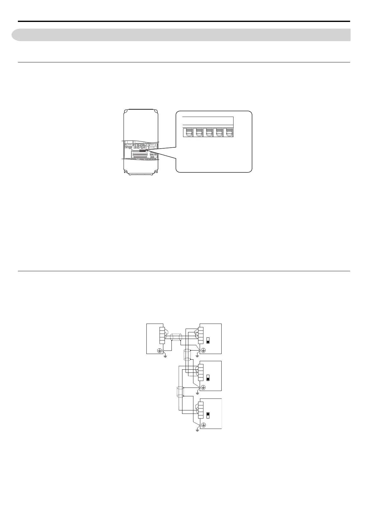
With the power shut off, connect the communications cable to the drive and the master. Use terminals TB5 for
MEMOBUS/Modbus.
Figure C.2
Figure C.2 Serial Communications Cable Connection Terminals (TB4)
Note: Separate the
communications cables from the main circuit cables and other wiring and power cables. Use shielded cables for the
communications cables, and properly shielded clamps to prevent problems with noise. When using RS-485 communications,
connect S+ to R+, and S- to R- as shown in the diagram below.
2. Check or set the termination resistor selection at all slaves. Use the description in Network Termination on
page 549 for slaves that are A1000 drives.
3. Switch the power on.
4. Set the parameters needed for serial communications (H5-01 through H5-12) using the digital operator.
5. Shut the power off and wait until the display on the digital operator goes out completely.
6. Turn the power back on.
7. The drive is now ready to begin communicating with the master.
Wiring Diagram for Multiple Connection
Figure C.3 and Figure C.4 explain the wiring diagrams for multiple connections using MEMOBUS/Modbus
communication.
RS-485 Interface
Figure C.3
Figure C.3 RS-485 Interface
Note: 1. Turn on the DIP switch S2 on the drive that is located at the end of the netwo
rk. All other slave devices must have this DIP switch set
to the OFF position.
2. Set H5-07 to “1” when using the RS-485 interface.
(TB4)
S-
S+
R-
R+
IG
Send (-)
Send (+)
Receive (-)
Receive (+)
Shield Ground
IG R+ R- S+ S-
Drive
Drive
Drive
S2
S2
S2
S–
S+
R–
R+
IG
S–
S+
R–
R+
IG
S–
S+
R–
R+
IG
R–
R+
S–
S+
IG
PLC
OFF
OFF
ON