B.3 Parameter Table
YASKAWA ELECTRIC SIEP C710616 27G YASKAWA AC Drive A1000 Technical Manual 505
o: Operator Related Settings
The o parameters are used to set up the digital operator displays.
o1: Digital Operator Display Selection
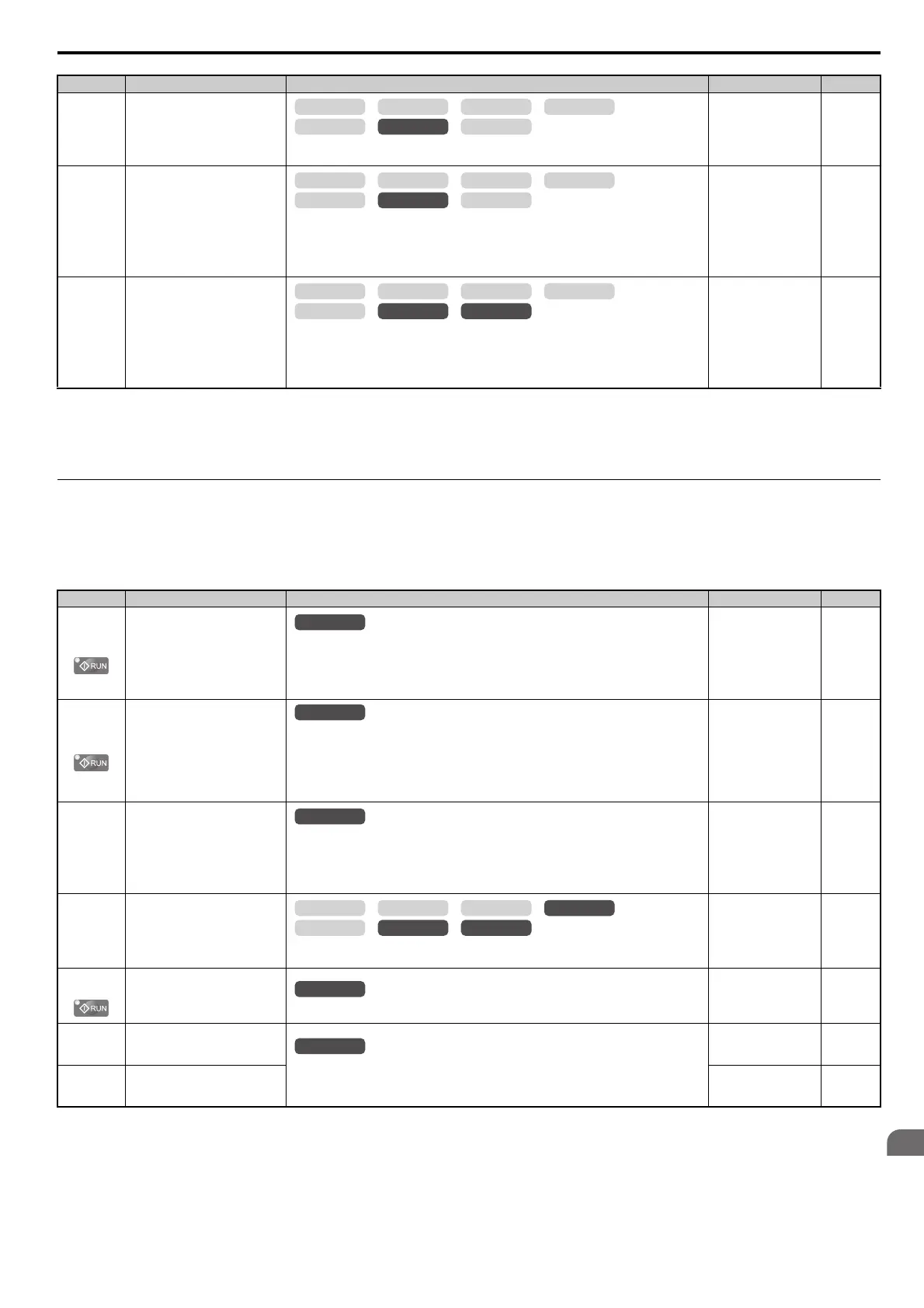
n8-69
(65DH)
Speed Calculation Gain
There is normally no need to change this parameter from the default value.
Sets the proportional gain for Speed Estimation.
Default: 1.00
Min: 0.00
Max: 20.00
312
n8-72
(655H)
Speed Estimation Method
Selection
There is normally no need to change this parameter from the default value.
Sets the method to be used for estimating the speed.
0: Conventional method
1: A1000 method
Note: This parameter is not available with models CIMR-A4A0930 and 4A1200.
Default: 1
Min: 0
Max: 1
313
n8-84
(2D3H)
Polarity Judge Current
Sets the current to determine polarity for the initial polarity calculation as a percentage of the
motor rated current.
100% = Motor rated current
Note: If an “Si” value is listed on the nameplate for a YASKAWA motor, n8-84 should be set to
“Si” value 2.
Default: 100%
Min: 0%
Max: 150%
313
<14> Default setting value is dependent on the motor code set to E5-01.
<17> Default setting is dependent on the speed estimation method selection (n8-72) as follows:
50.0 when n8-72 = 0
150.0 when n8-72 = 1
<18> Values shown here are for 200 V class drives. Double the value when using a 400 V class drive.
No. (Addr.) Name Description Setting Page
o1-01
(500H)
<10> Default setting is determined by the control mode (A1-02).
<36> Default setting value is determined by the digital operator display selection (o1-03).
Drive Mode Unit Monitor
Selection
Switches the display after the power has been turned on. When using an LED operator, pressing
the up arrow key will display the following data: frequency reference rotational direction
output frequency output current output voltage U1-.
(This is done by entering the 1 part of U1-. Certain monitors are not available in some
control modes.)
Default: 106 (Monitor
U1-06)
Min: 104
Max: 813
314
o1-02
(501H)
User Monitor Selection after
Power Up
o1-02 selects the information that is displayed when the power is turned on.
1: Frequency reference (U1-01)
2: Direction
3: Output frequency (U1-02)
4: Output current (U1-03)
5: User-selected monitor (set by o1-01)
Default: 1
Min: 1
Max: 5
314
o1-03
(502H)
Digital Operator Display Selection
Sets the units the drive should use to display the frequency reference and motor speed monitors.
0: 0.01 Hz
1: 0.01% (100% = E1-04)
2: min
-1
(calculated using the number of motor poles setting in E2-04, E4-04, or E5-04)
3: User-selected units (set by o1-10 and o1-11)
Default:
<10>
Min: 0
Max: 3
314
o1-04
(503H)
V/f Pattern Display Unit
0: Hz
1: min
-1
Default: <10>
Min: 0
Max: 1
315
o1-05
(504H)
LCD Contrast Control
Sets the brightness of the LCD operator (option).
Default: 3
Min: 0
Max: 5
315
o1-10
(520H)
User-Set Display Units Maximum
Va lu e
These settings define the display values when o1-03 is set to 3.
o1-10 sets the display value that is equal to the maximum output frequency.
o1-11 sets the position of the decimal position.
Default:
<36>
Min: 1
Max: 60000
315
o1-11
(521H)
User-Set Display Units Decimal
Display
Default:
<36>
Min: 0
Max: 3
315
No. (Addr.) Name Description Setting Page
OLV/PM AOLV/PM
CLV
V/f w/PG
CLV/PM
V/f OLV
OLV/PM AOLV/PM
CLV
V/f w/PG
CLV/PM
V/f OLV
OLV/PM AOLV/PM
CLV
V/f w/PG
CLV/PM
V/f OLV
All Modes
All Modes
OLV/PM AOLV/PM
CLV
V/f w/PG
CLV/PM
V/f OLV
All Modes
All Modes