B.3 Parameter Table
506 YASKAWA ELECTRIC SIEP C710616 27G YASKAWA AC Drive A1000 Technical Manual
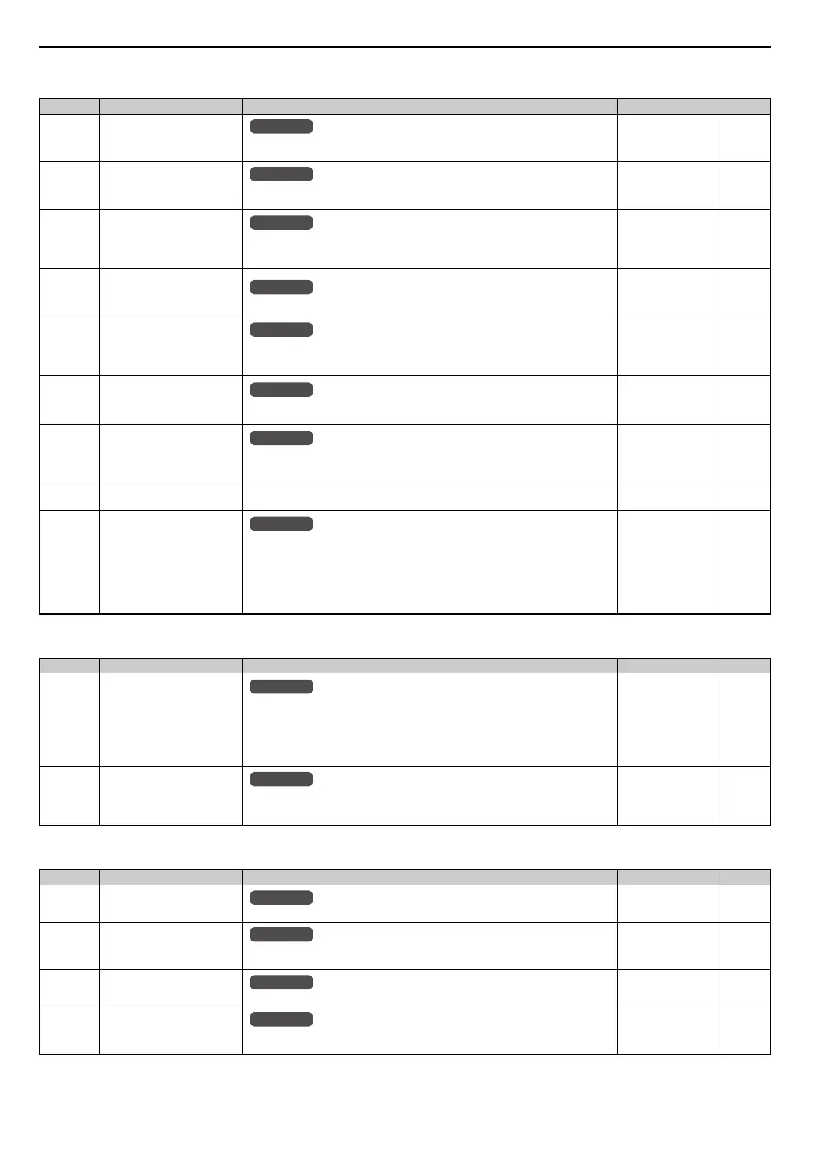
o2: Digital Operator Keypad Functions
o3: Copy Function
o4: Maintenance Monitor Settings
No. (Addr.) Name Description Setting Page
o2-01
(505H)
LO/RE Key Function Selection
0: Disabled
1: Enabled. LO/RE key switches between LOCAL and REMOTE operation.
Default: 1
Min: 0
Max: 1
315
o2-02
(506H)
STOP Key Function Selection
0: Disabled. STOP key is disabled in REMOTE operation.
1: Enabled. STOP key is always enabled.
Default: 1
Min: 0
Max: 1
316
o2-03
(507H)
User Parameter Default Value
0: No change.
1: Set defaults. Saves parameter settings as default values for a User Initialization.
2: Clear all. Clears the default settings that have been saved for a User Initialization.
Default: 0
Min: 0
Max: 2
316
o2-04
(508H)
Drive Model Selection
Enter the drive model. Setting required only if installing a new control board.
Default: Determined by
drive capacity
Min: –
Max: –
316
o2-05
(509H)
Frequency Reference Setting
Method Selection
0: ENTER key must be pressed to enter a frequency reference.
1: ENTER key is not required. The frequency reference can be adjusted using the up and down
arrow keys only.
Default: 0
Min: 0
Max: 1
317
o2-06
(50AH)
Operation Selection when Digital
Operator is Disconnected
0: The drive continues operating if the digital operator is disconnected.
1: A fault is triggered (oPr) and the motor coasts to stop.
Default: 0
Min: 0
Max: 1
317
o2-07
(527H)
Motor Direction at Power Up when
Using Operator
0: Forward
1: Reverse
This parameter requires that drive operation be assigned to the digital operator.
Default: 0
Min: 0
Max: 1
317
o2-09
(50DH)
Reserved – – –
o2-19
(61FH)
Selection of Parameter Write
During UV
Selects if parameter settings can be changed during a DC bus undervoltage condition. To be
used with 24V POWER SUPPLY (PS-A10L, PS-A10H).
0: Disabled
1: Enabled
Note: If the function of o2-19 is enabled, it is possible for a CPF06 Fault to occur. This function
should be used with 24V POWER SUPPLY (PS-A10L, PS-A10H) REVISION B or later.
If the older revision is used, parameter changes might not occur correctly.
Default
: 0
Min: 0
Max: 1
317
No. (Addr.) Name Description Setting Page
o3-01
(515H)
Copy Function Selection
0: Copy select
1: INV OP READ (Read parameters from the drive, saving them onto the digital operator.)
2: OP INV WRITE (Copy parameters from the digital operator, writing them to the drive.)
3: OP INV VERIFY (Verify parameter settings on the drive to check if they match the data
saved on the operator.)
To read the drive’ parameter settings into the digital operator, set o3-02 to 1 (to allow reading).
Default: 0
Min: 0
Max: 3
318
o3-02
(516H)
Copy Allowed Selection Selects whether the read operation (o3-01 = 1) is enabled or disabled.
0: Read operation prohibited
1: Read operation allowed
Default: 0
Min: 0
Max: 1
318
No. (Addr.) Name Description Setting Page
o4-01
(50BH)
Cumulative Operation Time
Setting
Sets the value for the cumulative operation time of the drive in units of 10 h.
Default: 0
Min: 0
Max: 9999
318
o4-02
(50CH)
Cumulative Operation Time
Selection
0: Logs power-on time
1: Logs operation time when the drive output is active (output operation time).
Default: 0
Min: 0
Max: 1
318
o4-03
(50EH)
Cooling Fan Operation Time
Setting
Sets the value of the fan operation time monitor U4-03 in units of 10 h.
Default: 0
Min: 0
Max: 9999
319
o4-05
(51DH)
Capacitor Maintenance Setting
Sets the point at which the cumulative timing for the main circuit capacitor maintenance starts.
View monitor U4-05 to determine when the capacitors may require replacement.
Default: 0%
Min: 0%
Max: 150%
319
All Modes
All Modes
All Modes
All Modes
All Modes
All Modes
All Modes
All Modes
All Modes
All Modes
All Modes
All Modes
 Loading...


