5.10 o: Operator Related Settings
YASKAWA ELECTRIC SIEP C710616 27G YASKAWA AC Drive A1000 Technical Manual 317
o2-05: Frequency Reference Setting Method Selection
Determines if the ENTER key must be pressed after changing the frequency reference using the digital operator while in
the Drive Mode.
Setting 0: ENTER key required
Every time the frequency reference is changed using the digital operator, the ENTER key must be pressed for the drive to
accept the change.
Setting 1: ENTER key not required
The output frequency changes immediately when the reference is changed by the up or down arrow keys on the digital
operator. The ENTER key does not need to be pressed. The frequency reference (Fref) is saved to memory after
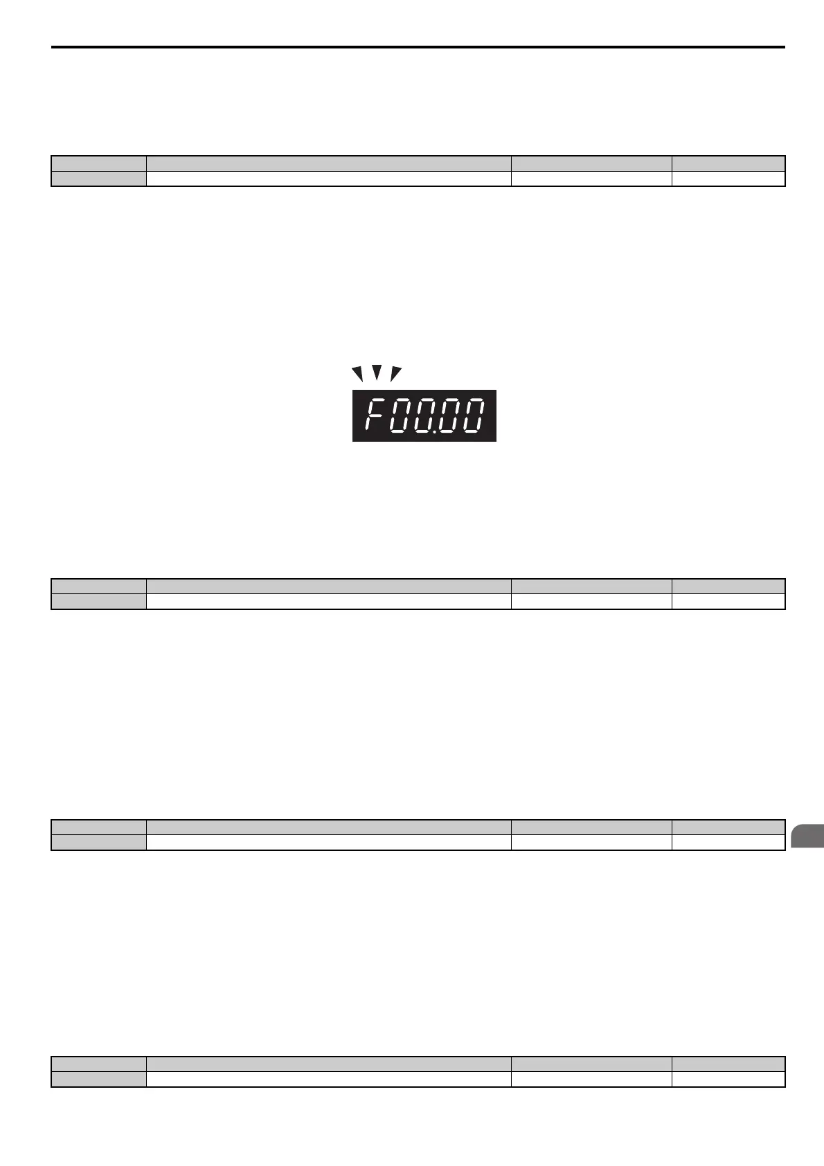
remaining unchanged for 5 seconds. The operator display flashes when settings can be made for the frequency reference.
Figure 5.112
Figure 5.112 Ready for Setting Frequency Reference
o2-06: Operation Selection when Digital Operator is Disconnected
Determines if the drive will stop when the remote control extension cable of the digital operator is removed in LOCAL
mode or when b1-02 or b1-16 is set to 0. When the operator is reconnected, the display will indicate that it was
disconnected.
Setting 0: Continue operation
The operation is continued.
Setting 1: Trigger a fault
The operation is stopped and an “oPr” fault is triggered. The motor coasts to stop.
o2-07: Motor Direction at Power Up when Using Operator
Determines the direction the motor will rotate after the drive is powered up and the Run command is given from the
digital operator.
Note: This parameter is effective only when the Run command is set to be given from the digital operator (b1-02, b1-16 = 0).
Setting 0: Forward
Setting 1: Reverse
o2-19: Selection of Parameter write During UV
Selects if parameter settings can be changed during a DC bus undervoltage condition. To be used with 24V POWER
SUPPLY (PS-A10L, PS-A10H).
Note: If the function of o2-19 is enabled, it is possible for a CPF06 Fault to occur. This function should be used with 24V POWER
SUPPLY (PS-A10L, PS-A10H) REVISION B or later. If the older revision is used, parameter changes might not occur correctly.
Setting 0: Disabled
Setting 1: Enabled
No. Name Setting Range Default
o2-05 Frequency Reference Setting Method Selection 0 or 1 0
No. Name Setting Range Default
o2-06 Digital Operator Disconnection Operation 0 or 1 0
No. Name Setting Range Default
o2-07 Motor Direction at Power Up when Using Operator 0 or 1 0
No. Name Setting Range Default
o2-19 Selection of Parameter Write During UV 0 or 1 0
 Loading...


