5.6 F: Option Settings
YASKAWA ELECTRIC SIEP C710616 27G YASKAWA AC Drive A1000 Technical Manual 231
F5: Digital Output Card Settings
These parameters set up the drive for operation with the digital output option card DO-A3. This section describes
parameters that govern operation with a digital output option card. Refer to the instruction manual packaged with the
option card for specific details on installation, wiring, input signal level selection, and parameter setup.
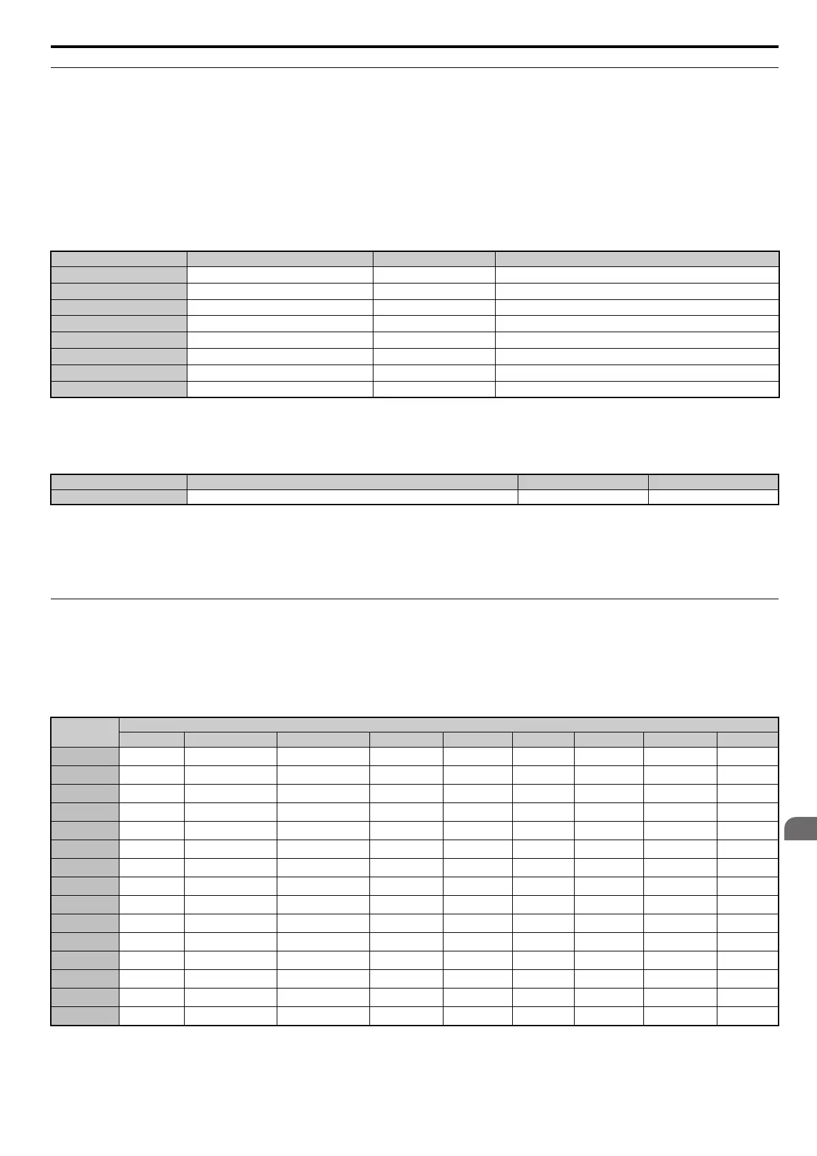
F5-01 through F5-08: Digital Output Option Card Terminal Function Selection
When F5-09 = 2, the parameters listed in the table below are used to assign functions to the output terminals on the
option card.
F5-09: DO-A3 Output Mode Selection
Determines how the DO-A3 option card is to work with the drive.
Note: Refer to TOBP C730600 41 YASKAWA AC Drive-Option Card DO-A3 Installation Manual for more details on F5-09 settings.
Setting 0: Separate output functions for each of 8 terminals
Setting 1: Binary output
Setting 2: Output functions assigned by F5-01 through F5-08
F6 and F7: Communication Option Card
These parameters are to configure communication option cards and communication fault detection methods.
Some parameters apply to all communication option cards, while some parameters are used
only for certain network
options.
No. Name Setting Range Default
F5-01
Terminal P1-PC Output Selection
0 to 192 0: During run
F5-02
Terminal P2-PC Output Selection
0 to 192 1: Zero speed
F5-03
Terminal P3-PC Output Selection
0 to 192 2: Speed agree
F5-04
Terminal P4-PC Output Selection
0 to 192 4: Frequency detection 1
F5-05
Terminal P5-PC Output Selection
0 to 192 6: Drive ready
F5-06
Terminal P6-PC Output Selection
0 to 192 37: During frequency output
F5-07
Terminal M1-M2 Output Selection
0 to 192 F: Not used
F5-08
Terminal M3-M4 Output Selection
0 to 192 F: Not used
No. Parameter Name Setting Range Default
F5-09 DO-A3 Output Mode Selection 0 to 2 0
Parameter
Communication Protocol
CC-Link MECHATROLINK-II MECHATROLINK-III PROFIBUS-DP CANopen DeviceNet LONWORKS Modbus TCP/IP EtherNet/IP
F6-01 to F6-03
F6-04 ––––––––
F6-06 to F6-08
F6-10, F6-11 ––––––––
F6-14
F6-20, F6-21 – ––––––
F6-22 – –––––––
F6-23 to F6-26 – ––––––
F6-30 to F6-32 – – – ––– – –
F6-35 to F6-36 – – – – –– – –
F6-50 to F6-63 – – – – – –––
F7-01 to F7-15 – – – – – – –
F7-16
F7-17 to F7-42 – – – – – – – –
F7-60 to F7-79 – – – ––– – –